Discharge lamp with a reflective mirror with optimized electrode configuration

a discharge lamp and electrode technology, applied in the direction of discharge tube luminescnet screen, coupling device connection, lighting and heating apparatus, etc., can solve the problem of temperature difference between the two electrodes, the normal halogen cycle no longer functions, and the lamp characteristics cannot be maintained, so as to reduce the temperature increase and reduce the erosion of the electrode

Inactive Publication Date: 2012-06-19
OSRAM GMBH
View PDF5 Cites 0 Cited by
  • Summary
  • Abstract
  • Description
  • Claims
  • Application Information

AI Technical Summary

Benefits of technology

[0005]The present invention solves the above problems and provides a discharge lamp with a reflective mirror which suppresses the temperature increase in the electrode on the opening part side of the reflective mirror and has little erosion of the electrode.
[0007]In the discharge lamp with a reflective mirror related to the present invention, the surface area of the F electrode can be larger than the surface area of the R electrode, and the temperature increase of the F electrode on the opening part side of the reflective mirror caused by the reflected light from the optical system of the projector can be suppressed by having the shapes of the F electrode and the R electrode before forming the melt electrodes satisfy any one of conditions (a) to (c) shown below or any combination of conditions (a) to (c) shown below. Thus, the halogen cycle functions normally, and the lamp characteristics can be maintained.

Problems solved by technology

Consequently, a temperature difference develops between the two electrodes, and the normal halogen cycle no longer functions.
As a result, sometimes, the electrode tip on the opening part side of the elliptical reflective mirror erodes, and the lamp characteristics cannot be maintained.
However, in the proposed method, a constant current pulse is always generated, and the halogen cycle is optimized, conversely, substantial damage to the electrode is possible.

Method used


Image

  • Discharge lamp with a reflective mirror with optimized electrode configuration
  • Discharge lamp with a reflective mirror with optimized electrode configuration
  • Discharge lamp with a reflective mirror with optimized electrode configuration

Examples


Embodiment Construction

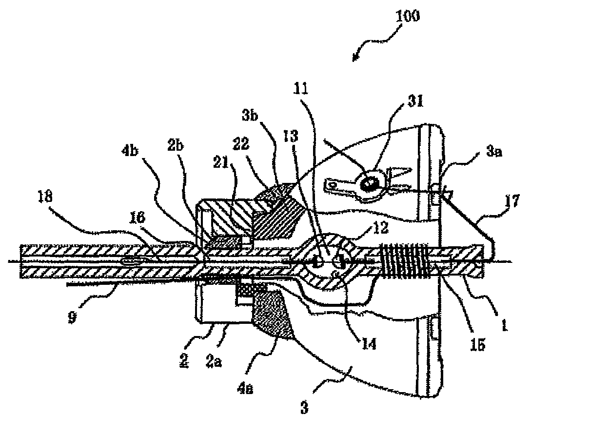
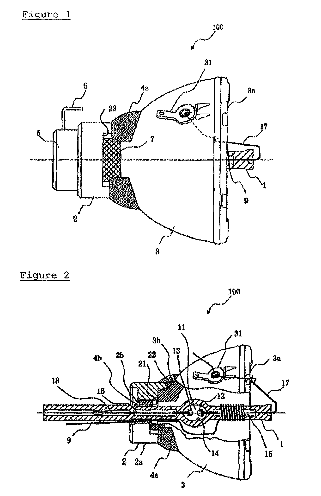
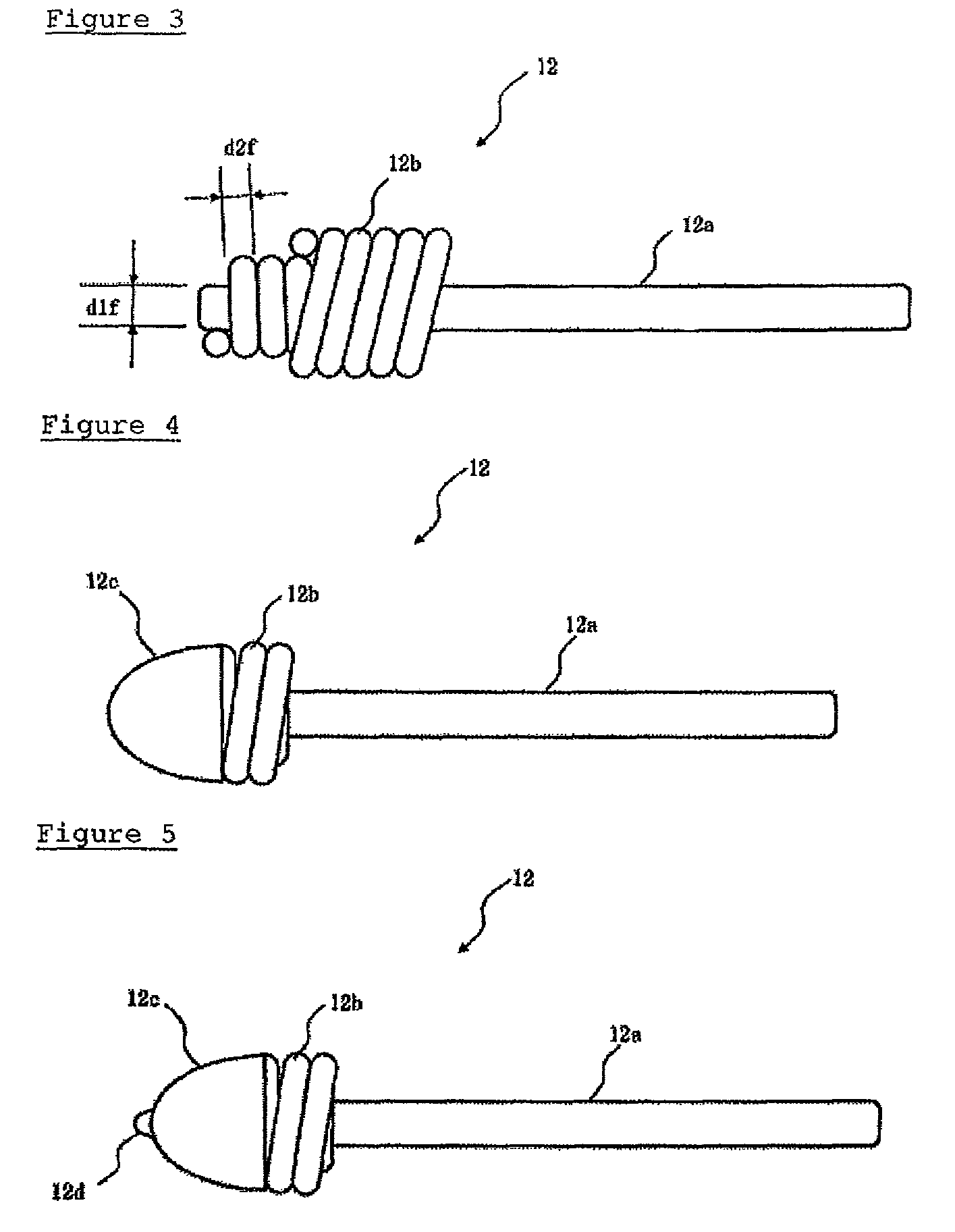
[0019]FIG. 1 is a structural diagram of a discharge lamp with a reflective mirror (100). FIG. 2 is a structural diagram of the discharge lamp with a reflective mirror (100) showing the cross section with a part cut away. FIG. 3 shows the structure of the F electrode (12) in the initial period of the manufacturing process. FIG. 4 is the diagram in which the tip of the F electrode (12) is melted to form the melt electrode (12c). FIG. 5 is the diagram in which the F electrode (12) is lit and the electrode tip (12d) is formed. FIG. 6 shows the vicinity of the F electrode (12) and the R electrode (13) in the light discharge tube (1). FIG. 7 is a conceptual view of the structure of the projector used in the simulation. FIG. 8 shows the result of the energy from the optical system returned to the light discharge tube (1) primarily in the structure in FIG. 7.

[0020]The embodiment features the electrodes positioned inside of the light discharge tube (1). Therefore, the entire structure of the...


PUM


Abstract

A discharge lamp configured to suppress temperature increases in the electrode on the opening part side of a reflective mirror is described. The discharge lamp includes an F electrode and an R electrode having shapes before forming the melt electrodes that satisfy at least one of the following conditions (a) to (c): (a) The diameter of the core wire of the F electrode is d1f, and the diameter of the core wire of the R electrode is d1r, then d1f>1.2×d1r; (b) The wire diameter of the coil of said F electrode is d2f, and the wire diameter of the coil of the R electrode is d2r, then d2f>1.2×d2r; (c) the number of windings of the coil of the F electrode is nf, and the number of windings of the coil of the R electrode is nr, then nf>1.2×nr.

Description

CROSS-REFERENCES TO RELATED APPLICATIONS[0001]This application claims the benefit of Japanese Patent Application No. 2008-223391, filed Sep. 1, 2008.TECHNICAL FIELD[0002]The present invention relates to a discharge lamp with a reflective mirror that is used in a projector.BACKGROUND[0003]Currently, an alternating-current (AC) discharge lamp with a reflective mirror (hereinafter, referred to as a lamp), particularly when combined with an elliptical reflective mirror, has an increase in the temperature of the electrode on the opening part side of the elliptical reflective mirror due to the reflected light from the optical system. Consequently, a temperature difference develops between the two electrodes, and the normal halogen cycle no longer functions. As a result, sometimes, the electrode tip on the opening part side of the elliptical reflective mirror erodes, and the lamp characteristics cannot be maintained. In addition, the electrode shape deforms and an offset of the arc spot is...

Claims


Application Information

Patent Timeline
Patent Type & Authority Patents(United States)
IPC IPC(8): H01J1/62F21Y101/00
CPCH01J61/0732
Inventor MATSUMOTO, HIDEYUKINOGUCHI, TAKASHI
Owner OSRAM GMBH
Why Eureka
Try Eureka