Stent body sock

a stent and body technology, applied in the field of stent body sock, can solve the problems of stents which are not properly secured or retained to the catheter, slipping of the stent, so as to achieve safe and effective stent release, easy retraction, and convenient retraction

Inactive Publication Date: 2012-06-26
BOSTON SCI SCIMED INC
View PDF19 Cites 15 Cited by
  • Summary
  • Abstract
  • Description
  • Claims
  • Application Information

AI Technical Summary

Benefits of technology

[0012]This invention provides an improvement over the prior art, by providing a stent delivery system which includes one or more stent retaining sleeves or socks which are constructed and arranged to retract off of the stent when the stent is expanded. The sleeves of the present invention are capable of retaining and immobilizing a non-crimped or crimped stent on the catheter surface by completely covering all or only a portion of the stent, the sleeves are readily retracted from off of the stent to provide for safe and effective stent release.

Problems solved by technology

It is well understood that stents which are not properly secured or retained to the catheter may slip and either be lost or be deployed in the wrong location or partially deployed.
In the past, crimping has been done by hand or by a crimping apparatus, often resulting in the application of undesired uneven forces to the stent.
Stents which have been crimped multiple times can suffer from fatigue and may be scored or otherwise marked which can cause thrombosis.
A poorly crimped stent can also damage the underlying balloon.

Method used


Image

  • Stent body sock
  • Stent body sock
  • Stent body sock

Examples


Embodiment Construction

[0021]While this invention may be embodied in many different forms, there are shown in the drawings and described in detail herein specific preferred embodiments of the invention. The present disclosure is an exemplification of the principles of the invention and is not intended to limit the invention to the particular embodiments illustrated.

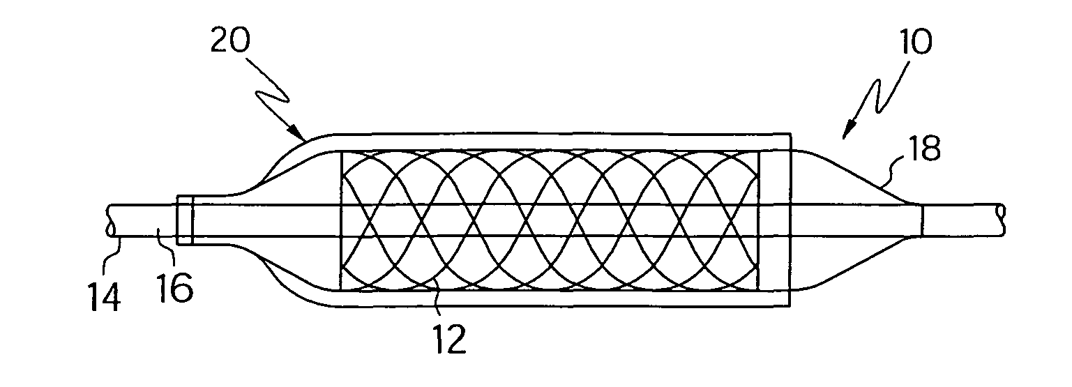
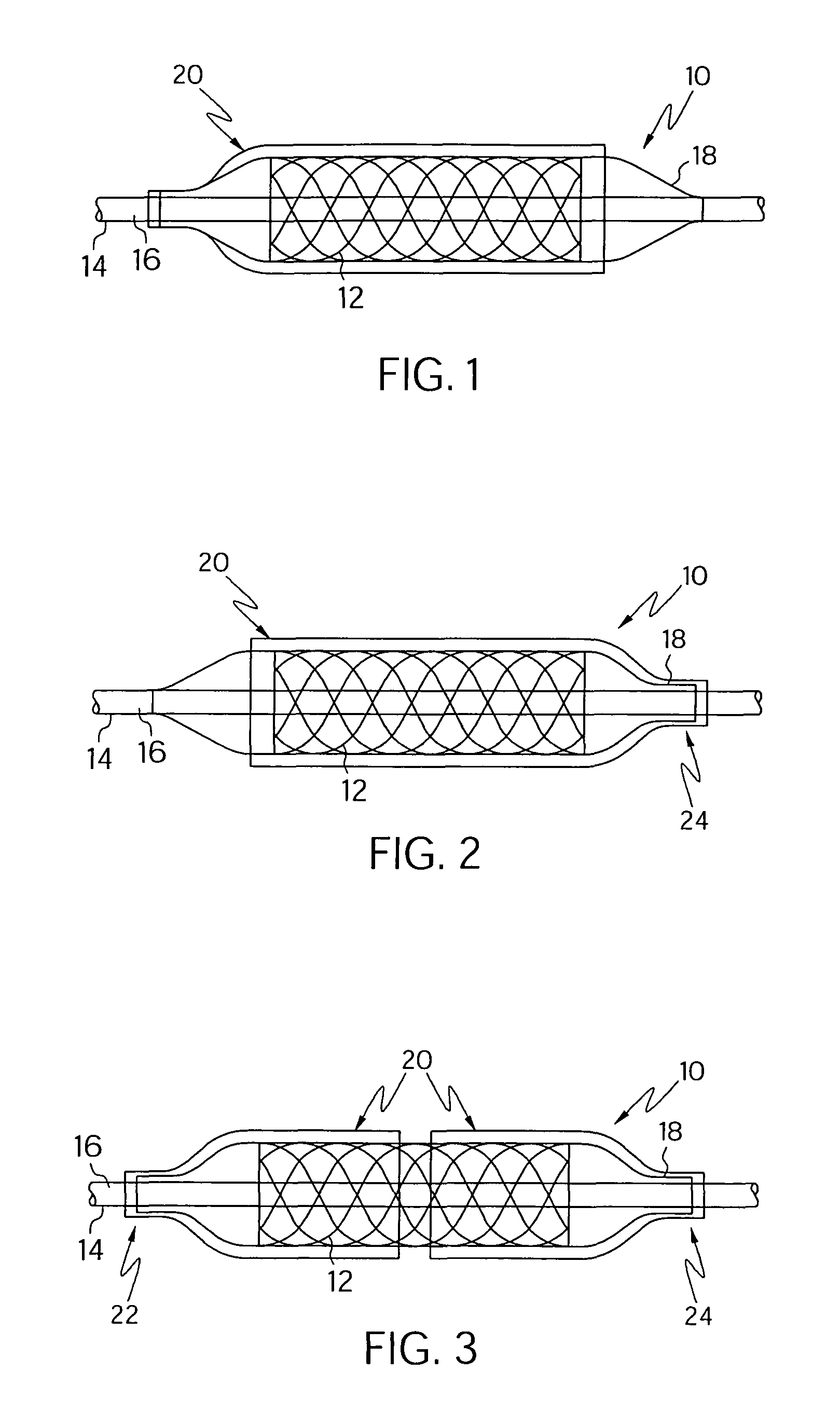
[0022]FIG. 1 shows a first embodiment of a stent delivery system, indicated generally at 10, which includes a stent 12 mounted upon a stent delivery catheter 14. FIG. 1 shows the stent delivery system prior to stent delivery. The stent delivery catheter 14 includes a catheter shaft 16 with and inflatable portion or balloon 18. A stent retaining sleeve 20 is engaged at a proximal portion 22 of the catheter shaft 16 adjacent to the balloon 18. The sleeve 20 extends distally over the stent 12 when in the unexpanded position. When the balloon 18 is expanded and the stent 12 expands from the unexpanded state to the expanded state, the sleeve 20 will...


PUM


Abstract

A stent delivery system which includes a stent delivery catheter, the stent delivery catheter having a stent mounting region, the stent mounting region having an inflatable portion. A stent is disposed about the stent mounting region, the stent having an unexpanded position and an expanded position. At least one stent retaining sleeve is also included having first and second ends, the first end being attached to the stent delivery catheter, the at least one stent retaining sleeve disposed about at least a portion of the stent in the unexpanded position, the stent retaining sleeve being constructed and arranged to retract toward the attached first end when the stent is expanded.

Description

CROSS-REFERENCE TO RELATED APPLICATIONS[0001]This application is a Continuation Application of U.S. application Ser. No. 09 / 970,458, filed on Oct. 2, 2001 now abandoned, which claims the benefit of U.S. Provisional Application 60 / 238,795, filed on Oct. 5, 2000, both of which are incorporated herein by reference in their entireties.STATEMENT REGARDING FEDERALLY SPONSORED RESEARCH[0002]Not ApplicableBACKGROUND OF THE INVENTION[0003]It is well understood that stents which are not properly secured or retained to the catheter may slip and either be lost or be deployed in the wrong location or partially deployed. Traditionally, in order to provide proper securement of the stent on the catheter the stent is crimped to a predetermined area of the catheter.[0004]In the past, crimping has been done by hand or by a crimping apparatus, often resulting in the application of undesired uneven forces to the stent. Such a stent must either be discarded or re-crimped. Stents which have been crimped m...

Claims


Application Information

Patent Timeline
Patent Type & Authority Patents(United States)
IPC IPC(8): A61F2/06A61F11/00A61F2/84
CPCA61F2/958A61F2002/9583
Inventor SEPPALA, JANDICAPRIO, FERNANDORIZQ, RAED
Owner BOSTON SCI SCIMED INC
Why Eureka
Try Eureka