Adjustable pulse width ground penetrating radar

a pulse width and radar technology, applied in the field of ground penetrating radar systems, can solve the problems of limiting the ability of deep penetration into the soil, less resolution, and limiting the ability of defining images objects

Active Publication Date: 2012-06-26
NIITEK
View PDF95 Cites 17 Cited by
  • Summary
  • Abstract
  • Description
  • Claims
  • Application Information

AI Technical Summary

Benefits of technology

[0008]In yet another embodiment, a ground penetrating radar system includes an antenna connected to a variable width pulse generator. The variable width pulse generator is operable to generate pulses at differing frequencies. The variable width pulse generator is formed by an avalanche transistor and a variable capacitor such that the pulse width of the variable width pulse generator is determined by the value of the variable capacitor. Control circuitry connected to the at variable pulse generator controls the pulse width of the pulse generator by controlling the value of the variable capacitor.

Problems solved by technology

However conductive attenuation and dissipative losses due to soil conditions and moisture increase dramatically with frequency, limiting the ability of to penetrate deeply into the soil.
Lower frequency radar yield less resolution than high frequency radar, thereby limiting its ability to define images objects.
Generally, however, objects of interest at greater depths are larger or multiple limiting the need for high resolution.

Method used


Image

  • Adjustable pulse width ground penetrating radar
  • Adjustable pulse width ground penetrating radar
  • Adjustable pulse width ground penetrating radar

Examples


Embodiment Construction

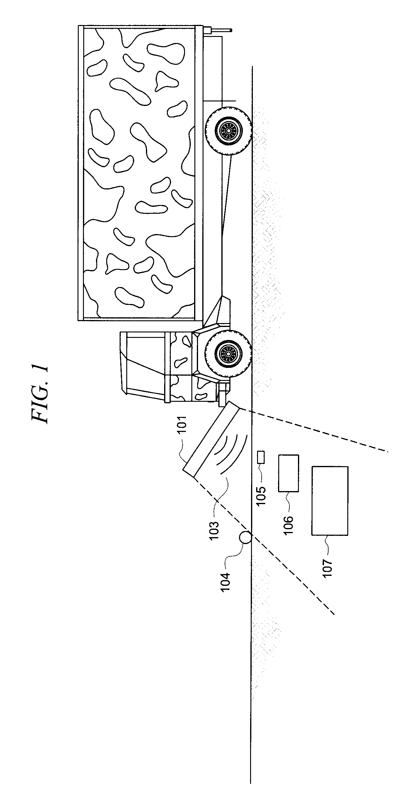
[0018]FIG. 1 is an illustration of a ground penetrating radar (GPR) unit 101 mounted to a vehicle 102. GPR unit 101 transmits radar pulses 103 which penetrate the ground in a survey area 104. Object 105, 106 and 107 reflect radar pulses 103, and these reflections are captured by GPR unit 101 and processed for display to an operator.

[0019]As discussed radar pulses 103 are absorbed, or dissipated, in the ground based on their frequency. Higher frequency pulses are dissipated quickly and therefore are unable to penetrate deeply into the survey area 104. Those higher frequency pulses may not penetrate to the depth of objects such as object 106 or 107. The high frequency pulses would, however provide high resolution as would be required to identify a small shallow object, such as object 105. Lower frequency pulses can penetrate to deeper into survey area 104 to image objects such as object 106 or 107, however, the resolution would not be as detailed as is possible with higher frequency p...


PUM


Abstract

A ground penetrating radar system is described that is able to create both low frequency, wide pulses, and high frequency, narrow pulses, to enable both deep and shallow operation of the ground penetrating radar on demand, including simultaneous operation.

Description

TECHNICAL FIELD[0001]This invention relates to ground penetrating radar systems and particularly to a system that can generate variable pulse width radar pulses to image both shallow objects and deep objects.BACKGROUND OF THE INVENTION[0002]Ground penetrating radar systems have been used for some time to image objects buried beneath the ground. As with all radar systems high frequency, or short pulse width radars are very good at providing detailed resolution of objects being imaged. However conductive attenuation and dissipative losses due to soil conditions and moisture increase dramatically with frequency, limiting the ability of to penetrate deeply into the soil.[0003]Lower frequency radar systems, or those with wide pulse widths are able to penetrate much more deeply into the ground as they are much less affected by the dissipative characteristics of the soil and sand. Lower frequency radar yield less resolution than high frequency radar, thereby limiting its ability to define ...

Claims


Application Information

Patent Timeline
Patent Type & Authority Patents(United States)
IPC IPC(8): G01S13/88
CPCG01S13/106G01S13/24G01S13/885G01S13/89
Inventor HIBBARD, MARKBANDELL, HOWARD
Owner NIITEK
Why Eureka
Try Eureka