
SAR autofocus for ground penetration radar

a technology of ground penetration radar and autofocus, which is applied in the direction of reradiation, measurement devices, instruments, etc., can solve the problems of difficult gpr autofocus solution, high azimuth resolution not achieved for most sar systems, and one autofocus solution may only be applicable to a small image block

Active Publication Date: 2014-01-16
RAYTHEON CO
View PDF11 Cites 11 Cited by
  • Summary
  • Abstract
  • Description
  • Claims
  • Application Information

AI Technical Summary

Benefits of technology

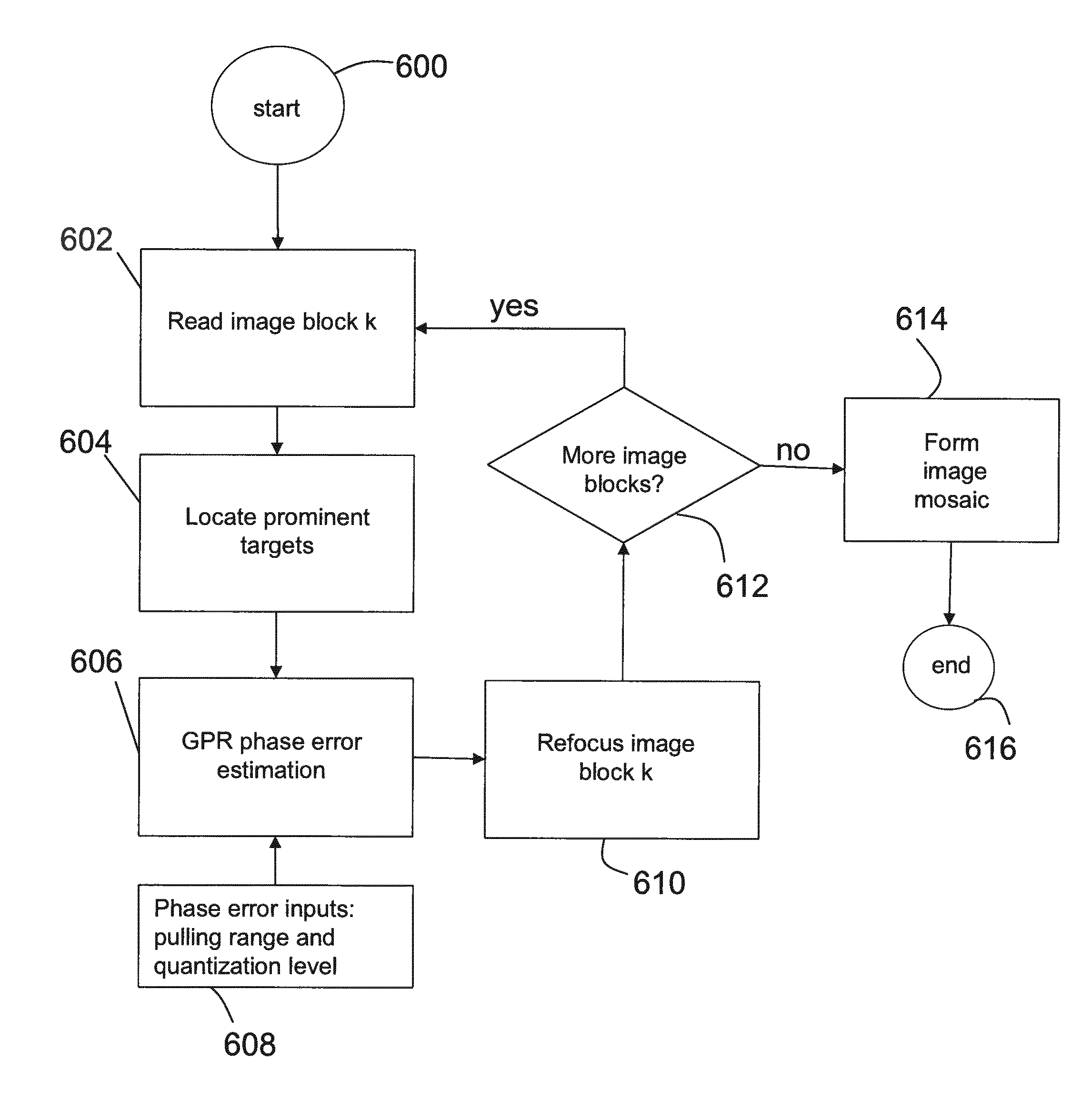
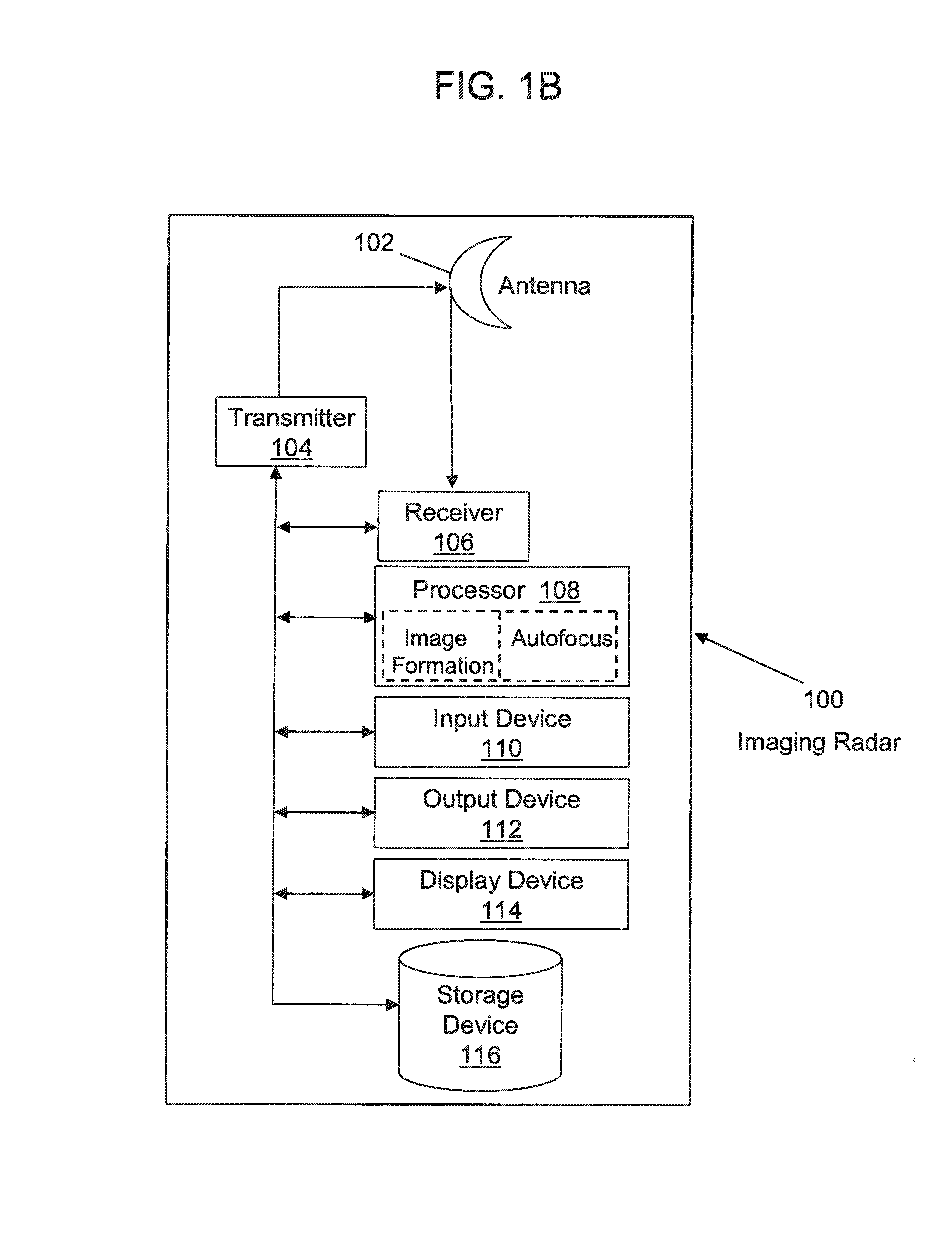
The present invention is related to an autofocus method for wide-beam / wide-band GPR ( ground penetration radar) that estimates target phase error directly from a complex ground image of high contrast targets. The method uses an antenna to transmit a signal and receive a reflected signal comprising multiple image blocks. The processor then reads each image block and locates prominent targets in each block, estimates ground penetration phase error by generating a 1D phase error and converting it into a 2D phase error of an image spectra, refocuses each image block according to the estimated phase error, and creates an image mosaic by combining each refocused image block. The estimated phase error is modeled by the superposition of a one-dimensional Fourier series of limited order. The system includes an antenna and a processor programmed to estimate the phase error and refocus the image blocks accordingly. The technical effect of this invention is to provide an efficient and accurate method for autofocus in ground penetration radar that ensures the target is always in focus.

Problems solved by technology

However, high azimuth resolution is not achieved for most SAR systems, since a costly high performance navigation system would be required, as well as accurate knowledge of the terrain elevation.
However, though there are some autofocus solutions for various narrow band and narrow beam SAR systems, the autofocus solution for GPR remains a challenging problem due to several factors.
But, for a wide beam SAR, one autofocus solution may only be applicable to a small image block.
In range compressed data, it is difficult to extract a target signal directly or after a simple data deskew process.
Therefore, identifying prominent targets or estimating phase error cannot be efficiently performed in the range compressed data set.
Third, the strength of the prominent targets in GPR is usually not as high as other high frequency SAR.
This leads to the need for highly sensitive phase error estimation algorithms, such as maximum likelihood estimation or contrast optimization.

Method used


Image

  • SAR autofocus for ground penetration radar
  • SAR autofocus for ground penetration radar
  • SAR autofocus for ground penetration radar

Examples


Embodiment Construction

[0046]An embodiment of the present invention provides a method for autofocus for wide-beam / wide-band ground penetration radar (GPR), where the wide beam angle makes the phase error highly spatially varying. This method estimates target phase error directly from the complex ground image of high contrast targets. A focused image is then obtained by removing the estimated phase error from the spatial frequency spectra of the complex image. The phase error of the imaged targets is modeled by the superposition of a one-dimensional Fourier series of limited order. Each component of the phase error is estimated from the two-dimensional spatial (ground) frequency spectra through 2D to 1D mapping. Optimal phase error is obtained by means of a contrast optimization method.

[0047]Embodiments of this method overcome some of the challenges of GPR autofocus. First, to overcome spatially varying phase error, the GPR image is divided into multiple image blocks in order for each image block to be ref...


PUM


Abstract

A method of synthetic aperture radar autofocus for ground penetration radar (100). The method includes transmitting a signal via an antenna (102); receiving a reflected signal comprising a plurality of image blocks via the antenna (102); reading each image block from the reflected signal (602) via a processor (108); locating prominent targets in each image block (604) via the processor (108); estimating ground penetration phase error (606) via the processor (108) in each image block via phase error inputs (608) including pulling range and quantization level by generating a 1D phase error (706) and converting the 1D phase error into a 2D phase error of an image spectra (708); refocusing each image block according to estimated ground penetration phase error for that image block (610) via the processor (108); and forming an image mosaic comprising each refocused image block (614) via the processor (108).

Description

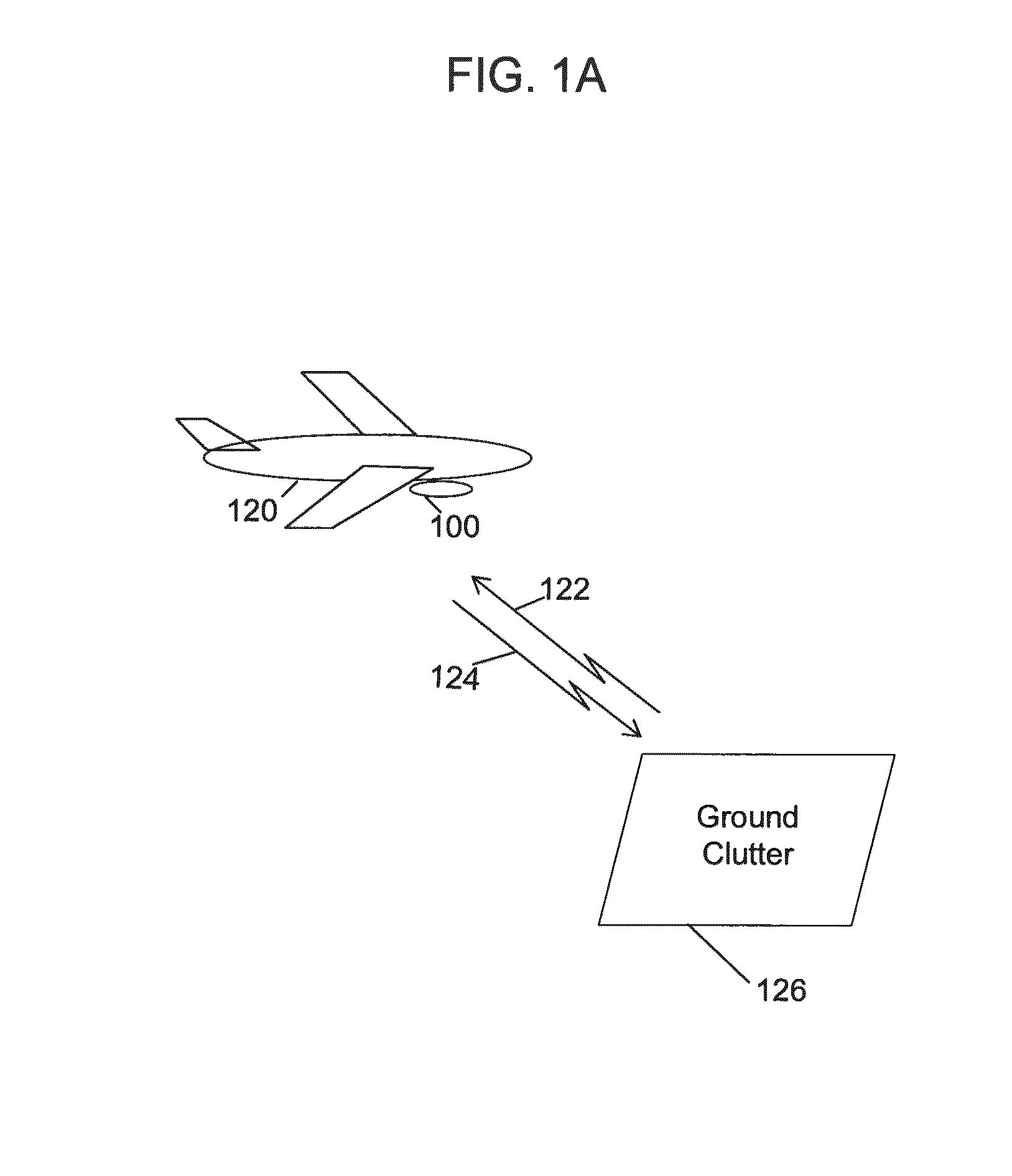
STATEMENT REGARDING FEDERALLY SPONSORED RESEARCH OR DEVELOPMENT[0001]This invention is related to U.S. Government contract number H94003-04D-0006 Task Order 0185 (Hawkeye (Ground Penetrating Synthetic Aperture Radar (GPSAR)) Vertical Take Off and Landing). The U.S. Government has certain rights in this invention.BACKGROUND[0002]1. Field[0003]The present invention is related to autofocus for ground penetration radar (“GPR”), and more particularly to, autofocus for wide-beam / wide-band GPR.[0004]2. Description of Related Art[0005]Synthetic aperture radar (“SAR”) is used for ground mapping as well as target identification, where a moving platform, e.g., an aircraft, has an imaging radar that sends transmitted signals from different positions along the path of the platform such that the ground (e.g., ground clutter) reflects signals that are received by the imaging radar.[0006]To achieve high azimuth resolution in SAR image formation, the slant range history of the processed target must ...

Claims


Application Information

Patent Timeline
Patent Type & Authority Applications(United States)
IPC IPC(8): G01S13/90
CPCG01S13/9035G01S13/885G01S13/90G01S13/904G01S13/9019
Inventor JIN, MICHAEL Y.
Owner RAYTHEON CO
Learn More