Cooler with LED lighting

a cooler and led light technology, applied in the field of portable beverage coolers, can solve the problems of not solving all the problems of illuminating a portable cooler, light source is completely useless for application to the cooler, fluorescent bulbs are extremely fragile, etc., and achieve the effect of reducing power consumption

Active Publication Date: 2012-07-03
LIDDUP
View PDF9 Cites 36 Cited by
  • Summary
  • Abstract
  • Description
  • Claims
  • Application Information

AI Technical Summary

Benefits of technology

[0014]The cooler of the present invention resolves the problems associated with prior art coolers by providing a cooler that utilizes multiple light emitting diodes (“LED”) to illuminate the entire interior of the cooler by unique placement of the LEDs which allows for a minimal number of LEDs to minimize power consumption. The LEDs are activated by a magnetic reed switch positioned between an inside liner and an outer liner of the cooler. A magnet of the magnetic reed switch is positioned in the lid. A magnetic field of the magnet is in an activating location when the lid is in an open state wherein the magnetic reed switch completes a circuit from a battery to the LEDs thereby allowing the LEDs to illuminate the entire interior of the chamber of the cooler. Each of the LEDs is preferably positioned along an upper region of the main body in which the upper region extends from an upper edge of the main body to 2 inches below the upper edge. The interior chamber preferably has a volume ranging from 40 quarts to 50 quarts. The LEDs can preferably illuminate the interior chamber of the cooler for at least four hours of continuous use.

Problems solved by technology

This light source is completely useless for application to a cooler since it directly takes away from the basic functionality of a cooler.
Also, fluorescent bulbs are extremely fragile, with the possibility of breakage upon closing of the lid which would expose the hazardous gas and mercury within the cooler.
The prior art, although providing various means for illuminating a cooler, has still not addressed all of the problems with illuminating a portable cooler.

Method used


Image

  • Cooler with LED lighting
  • Cooler with LED lighting
  • Cooler with LED lighting

Examples


Embodiment Construction

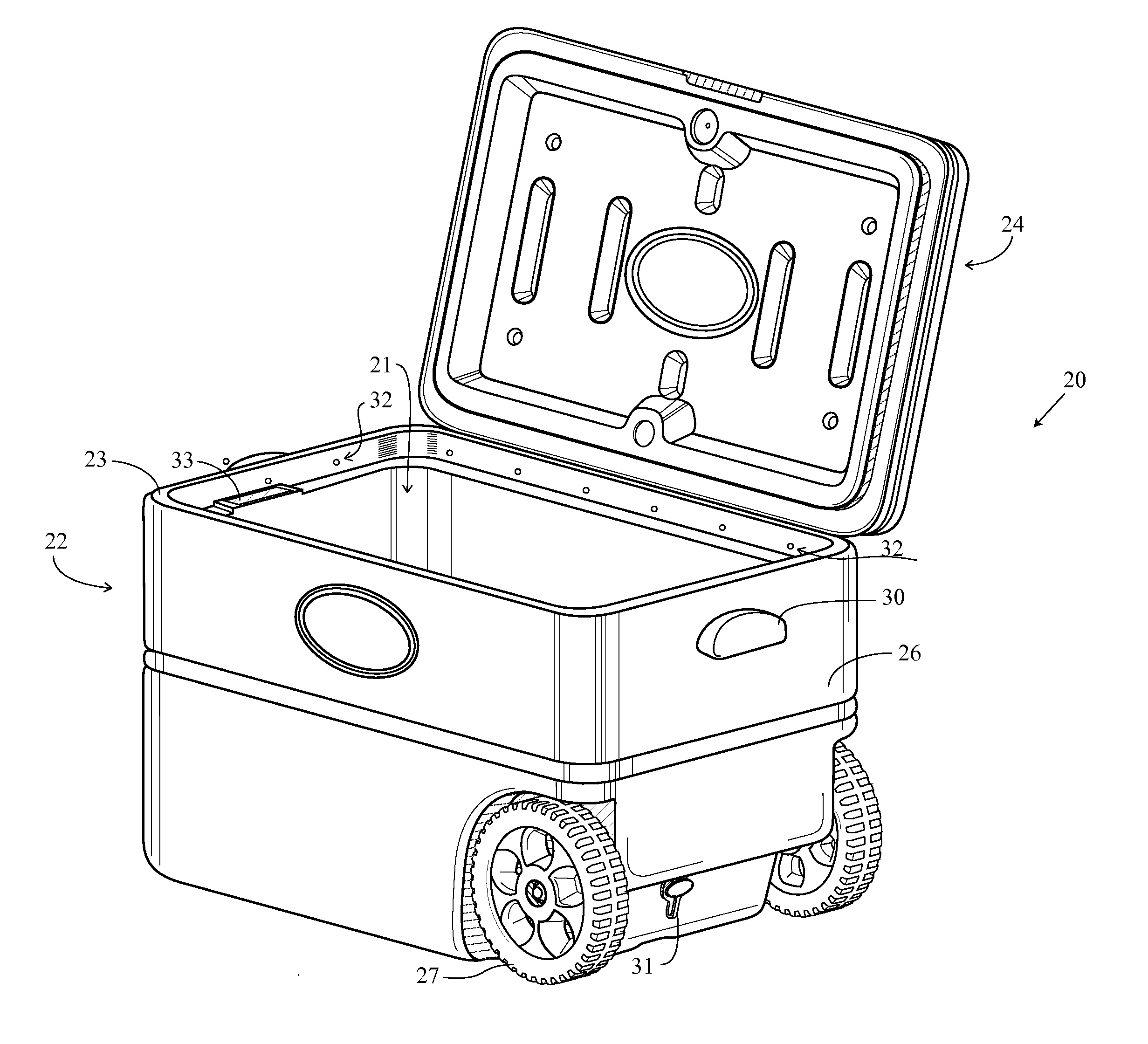
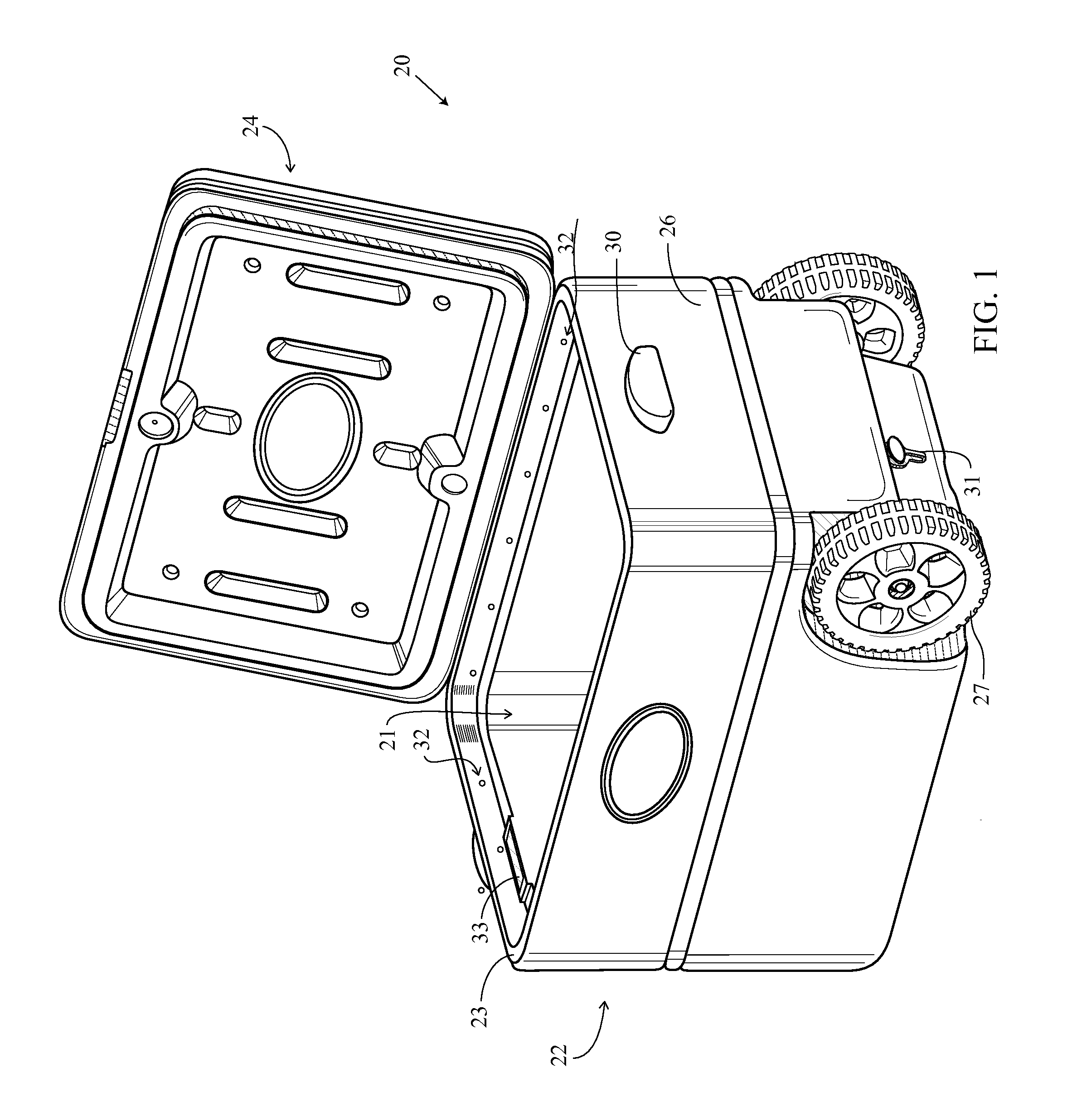
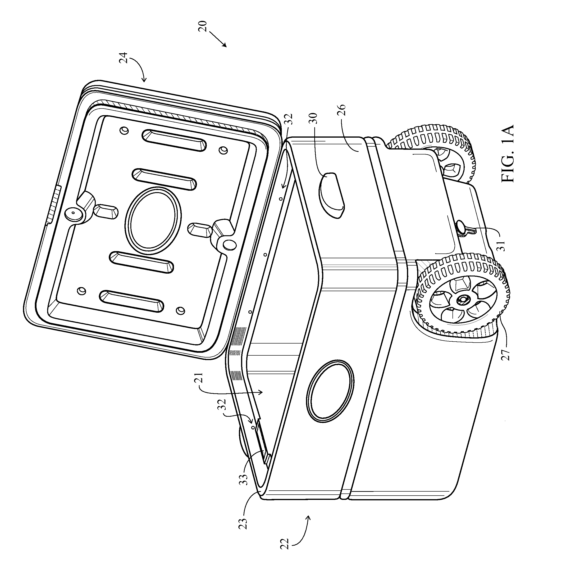
[0039]As shown in FIGS. 1 and 1A, the present invention is directed to a portable cooler 20 having a lid 24 and a main body 22 having an interior chamber 21. The lid 24 is preferably made of high density polyethylene (HDPE). The main body 22 comprises an outer liner 26 and an inner liner 34 that defines an interior chamber 21. The lid 24 is attached to the main body 22, and the lid 24 movable from a closed state to an open state. Multiple LEDs 32 are positioned along an upper region of the main body 22. Each of the plurality of LEDs 32 has a millicandela ranging from 4000 to 20000. The cooler 20 also preferably has a pair of wheels 27 and a drain plug 31.

[0040]The cooler 20 further comprises at least one battery 41, positioned within a battery compartment, for providing power to each of the plurality of LEDs 32. The battery 41, not shown, preferably has a battery cover with backing made of polypropylene (PP). The preferred thickness of the wall of the backing is approximately 0.100 ...


PUM


Abstract

A cooler that utilizes multiple LEDs to illuminate an entire interior is disclosed herein. The LEDs are activated by a magnetic reed switch positioned between an inside liner and an outer liner of the cooler. A magnet is positioned in a lid. Removal of the magnetic field of the magnet when the lid is in an open state allows the magnetic reed switch to complete a circuit from a battery to the LEDs thereby allowing the LEDs to illuminate the entire interior chamber of the cooler.

Description

CROSS REFERENCE TO RELATED APPLICATION[0001]The Present application is a continuation application of U.S. patent application Ser. No. 13 / 010,078, filed Jan. 20, 2011, and claims priority to U.S. Provisional Patent Application No. 61 / 424,618, filed on Dec. 17, 2010, both of which are hereby incorporated by reference in their entireties.STATEMENT REGARDING FEDERALLY SPONSORED RESEARCH OR DEVELOPMENT[0002]Not ApplicableBACKGROUND OF THE INVENTION[0003]1. Field of the Invention[0004]The present invention generally relates to portable beverage coolers.[0005]2. Description of the Related Art[0006]The prior art discusses various coolers, including coolers with lighting.[0007]Winslow, U.S. Pat. No. 4,754,376 for an Automatic Ice Chest Light discloses a lighting device (light bulb) attached to n interior surface of a lid of an ice chest that is automatically activated when the lid is raised and deactivates when the lid is closed by way of a mercury switch.[0008]Bania, U.S. Pat. No. 6,182,462...

Claims


Application Information

Patent Timeline
Patent Type & Authority Patents(United States)
IPC IPC(8): F21V33/00
CPCF21V23/04F25D27/005A45C5/14A45C11/20A45C15/06F21Y2101/02Y10S362/802F21Y2115/10F21S9/03F21V23/0442F21V3/02F21V33/008F21S4/28B65D81/3816B65D85/72B65D43/16B65D25/28F25D3/06F25D23/12F21Y2103/10F25D2700/02
Inventor SANDBERG, JAYSON T.
Owner LIDDUP
Why Eureka
Try Eureka