LED lens array optic with a highly uniform illumination pattern

a technology of light-emitting diodes and lens arrays, applied in the field of led (light-emitting diodes) arrays and lens array optics, can solve problems such as light loss, and achieve the effect of high uniformity

Active Publication Date: 2012-07-03
DIALIGHT CORP
View PDF3 Cites 29 Cited by
  • Summary
  • Abstract
  • Description
  • Claims
  • Application Information

AI Technical Summary

Benefits of technology

[0006]To meet these illumination requirements with the least number of LEDs, a new optical system must be designed. The invention herein creates an optical system that redistributes the LED light to satisfy the needs of general illumination applications. This minimizes the number of LEDs and results in a cost effective light fixture.
[0008]Accordingly, one object of the present invention is to provide a novel LED illumination device that can generate a highly uniform illumination pattern appropriate for general illumination applications.
[0009]The present invention achieves the above-noted results by incorporating an array of negative lenses into a light cover. Normally light losses result due to the optic and the light cover. In the present invention there are only one set of light losses because the lens optic is integrated into the light cover. An array of LEDs is positioned behind the array of negative lenses. With the arrangement described herein, the higher intensity light emitted mainly forward of the LEDs is diverted away from the central axis by the negative lenses. The lens width is limited and therefore the wide angle light emitted by the LEDs is not diverted by the lenses. The dimensions of the negative lenses as well as the distance between the LEDs and the negative lenses are therefore controlled.

Problems solved by technology

Normally light losses result due to the optic and the light cover.

Method used


Image

  • LED lens array optic with a highly uniform illumination pattern
  • LED lens array optic with a highly uniform illumination pattern
  • LED lens array optic with a highly uniform illumination pattern

Examples


Embodiment Construction

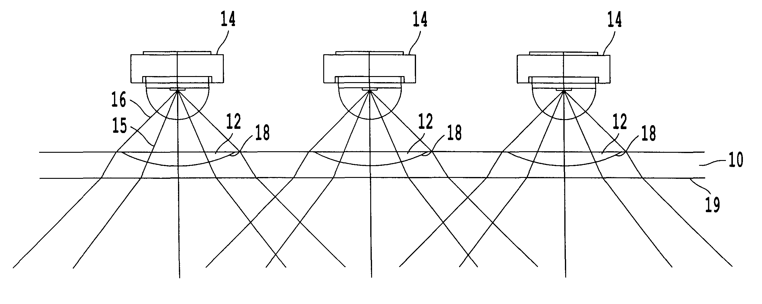
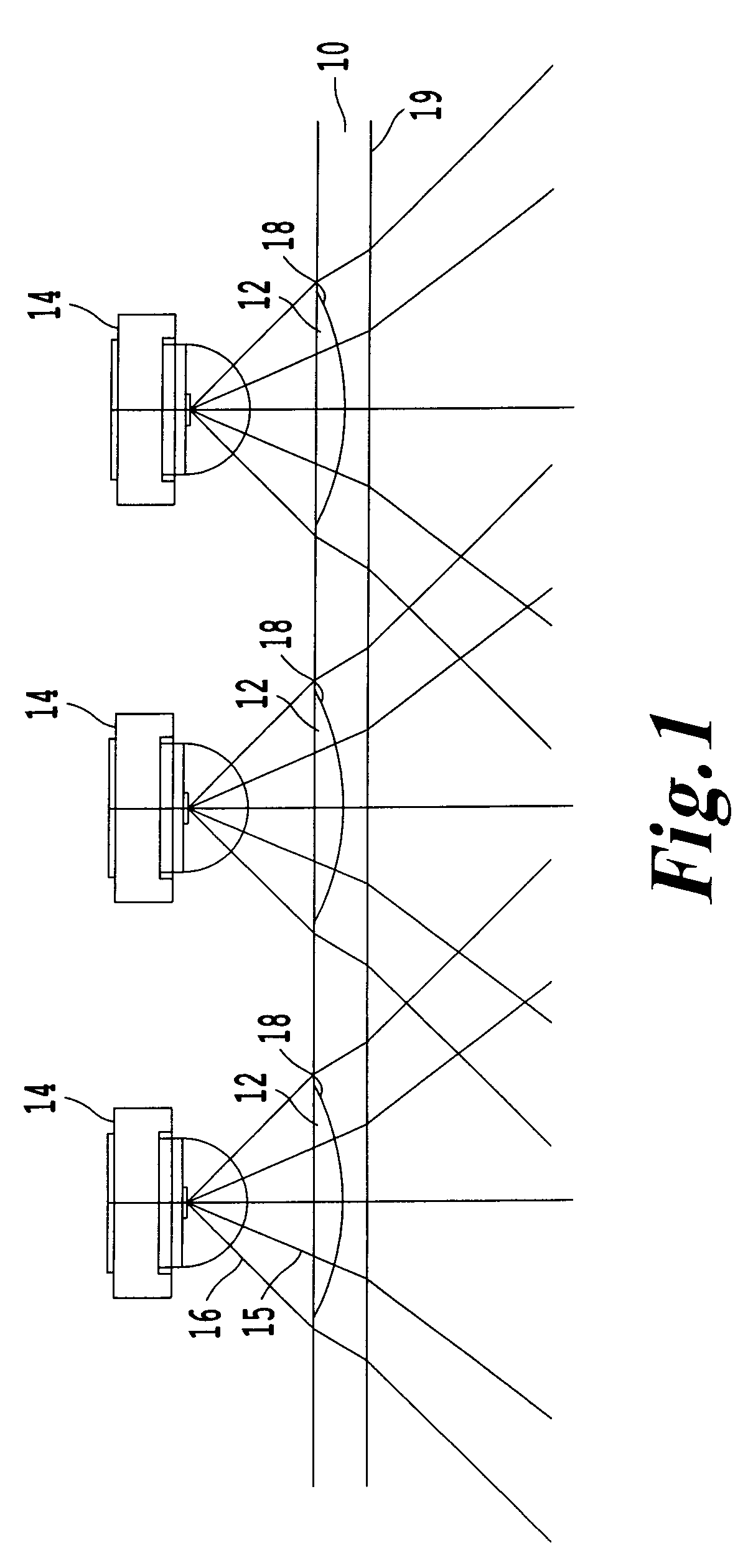
[0023]Referring now to the drawings, wherein like reference numerals designate identical or corresponding parts throughout the several views, and more particularly to FIG. 1, an embodiment of an LED illumination device of the present invention is shown.

[0024]As shown in FIG. 1, an LED illumination device of the present invention includes a light cover 10 with an integrated array of negative lenses 12, each with a negatively powered lens surface 18, positioned forward of an LED array formed of a plurality of LEDs 14. The light cover 10 also has a second surface 19. The integrated array of negative lenses 12 are formed by removing material from the light cover 10. That is, each negative lens 12 is a portion of the lens cover 10 where material is absent. This would typically be done by incorporating the lens features of the negative lenses 12 into a mold that is used to make the light cover 10. The light cover 10 could be made of plastic or glass. Examples of moldable plastic materials...


PUM


Abstract

An LED (light emitting diode) illumination device that can generate a uniform light output illumination pattern. The illumination source includes an array of LEDs. Forward of the LEDs is an array of negative lens surfaces. At a distance from the LED the width W of the lens and the spacing D between the LEDs enhances creating the uniform light output illumination pattern. The negative lens surface can be non-symmetric and take a conic or conic-like shape.

Description

BACKGROUND OF THE INVENTION[0001]1. Field of the Invention[0002]The present invention is directed to an LED (light emitting diode) array and lens array optic that creates a highly uniform illumination pattern.[0003]2. Discussion of the Background[0004]Due to mediocre light output, LED use in the past was primarily limited to applications where only small surface areas were illuminated. In these applications the light was concentrated into a narrow beam using an optic designed to take the wide angle light output of an LED and collimate it using a lens, discussed below with respect to FIG. 3. For high-power LEDs the collimation was accomplished using a secondary optic. Due to cost reductions and performance improvements LEDs can now be used in general illumination where large surface areas are illuminated. Examples of these applications include parking garages, parking lots, and roadways. These new applications require different optical designs. In particular these applications requir...

Claims


Application Information

Patent Timeline
Patent Type & Authority Patents(United States)
IPC IPC(8): F21V1/00F21V5/00
CPCF21V5/007F21V5/04G02B3/0037F21W2131/103F21Y2101/02F21Y2115/10
Inventor PECK, JOHN P.SHASTRY, CHAKRAKODI V.
Owner DIALIGHT CORP
Why Eureka
Try Eureka