Prosthesis cutting guide, cutting tool and method

a cutting guide and prosthesis technology, applied in the field of orthopaedics, can solve the problems of slow and tedious process, osteoarthritis or rheumatoid arthritis in the joint replacement surgery, etc., and achieve the effect of improving the imprint or location of the pocket, improving the location and accuracy of the pock

Inactive Publication Date: 2012-07-03
DEPUY PROD INC
View PDF58 Cites 36 Cited by
  • Summary
  • Abstract
  • Description
  • Claims
  • Application Information

AI Technical Summary

Benefits of technology

[0015]The technical advantage of the present invention includes an improved imprint or location of the pocket for the prosthesis. For example, according to one aspect of the present invention, the guide includes channels positioned about the outer periphery of the guide, which conform to the outer periphery of the pocket for placing for a pocket with an outer periphery that is well defined and accurate. Thus, the present invention provides for an improved and accurate location of the pocket for the prosthesis.
[0016]Another technical advantage of the present invention includes an improved accuracy in the depth of the pocket into which the implant is to be located. For example, according to one aspect of the present invention, the tool includes a collar, which cooperates with the guide when the tool is placed in the channels of the guide. The collar on the tool seats against the rim around the channels and provides for an accurate and consistent depth of the pocket for the implant.
[0017]The technical advantages of the present invention further include the ability to form the pocket for an implant in much greater speed and precision. For example, according to one aspect of the present invention, the guide includes a plurality of spaced apart channels. These channels occupy most of the cross-sectional area of the guide. The guide, in cooperation with the tool, is used to form most of the pocket for the implant. Only a quick and simple use of a small osteotome to remove the small portions of material remaining after the utilization of the burr tool and guide, is required and that can be quickly accomplished. Therefore, with the rapid use of the guide and the burr tool and the minimal use of the osteotome, the pocket may be prepared very quickly and accurately.

Problems solved by technology

Such patients of joint replacement surgery typically suffer from osteoarthritis or rheumatoid arthritis.
This process is very slow and tedious in order to achieve a precise and accurate fit in all dimensions.

Method used


Image

  • Prosthesis cutting guide, cutting tool and method
  • Prosthesis cutting guide, cutting tool and method
  • Prosthesis cutting guide, cutting tool and method

Examples


Embodiment Construction

[0047]Embodiments of the present invention and the advantages thereof are best understood by referring to the following descriptions and drawings, wherein like numerals are used for like and corresponding parts of the drawings.

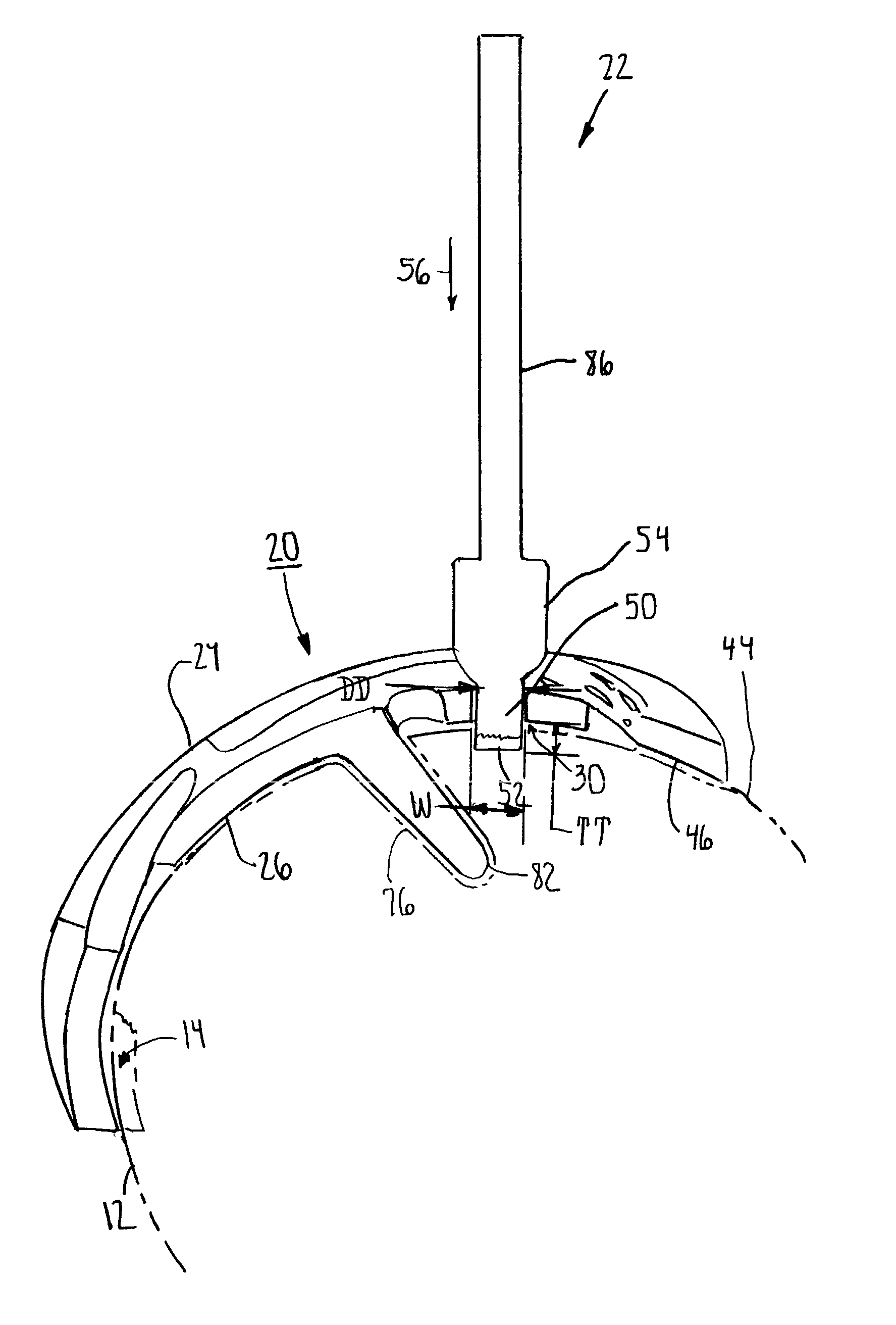
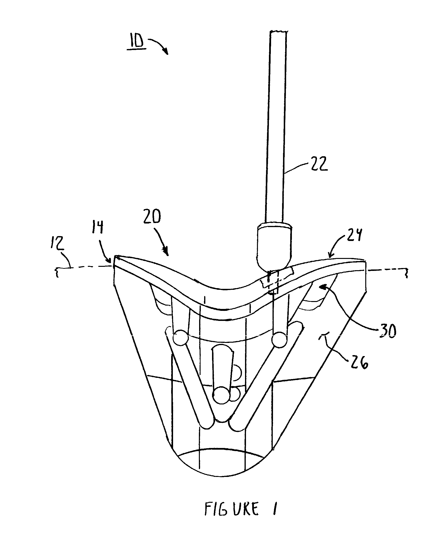
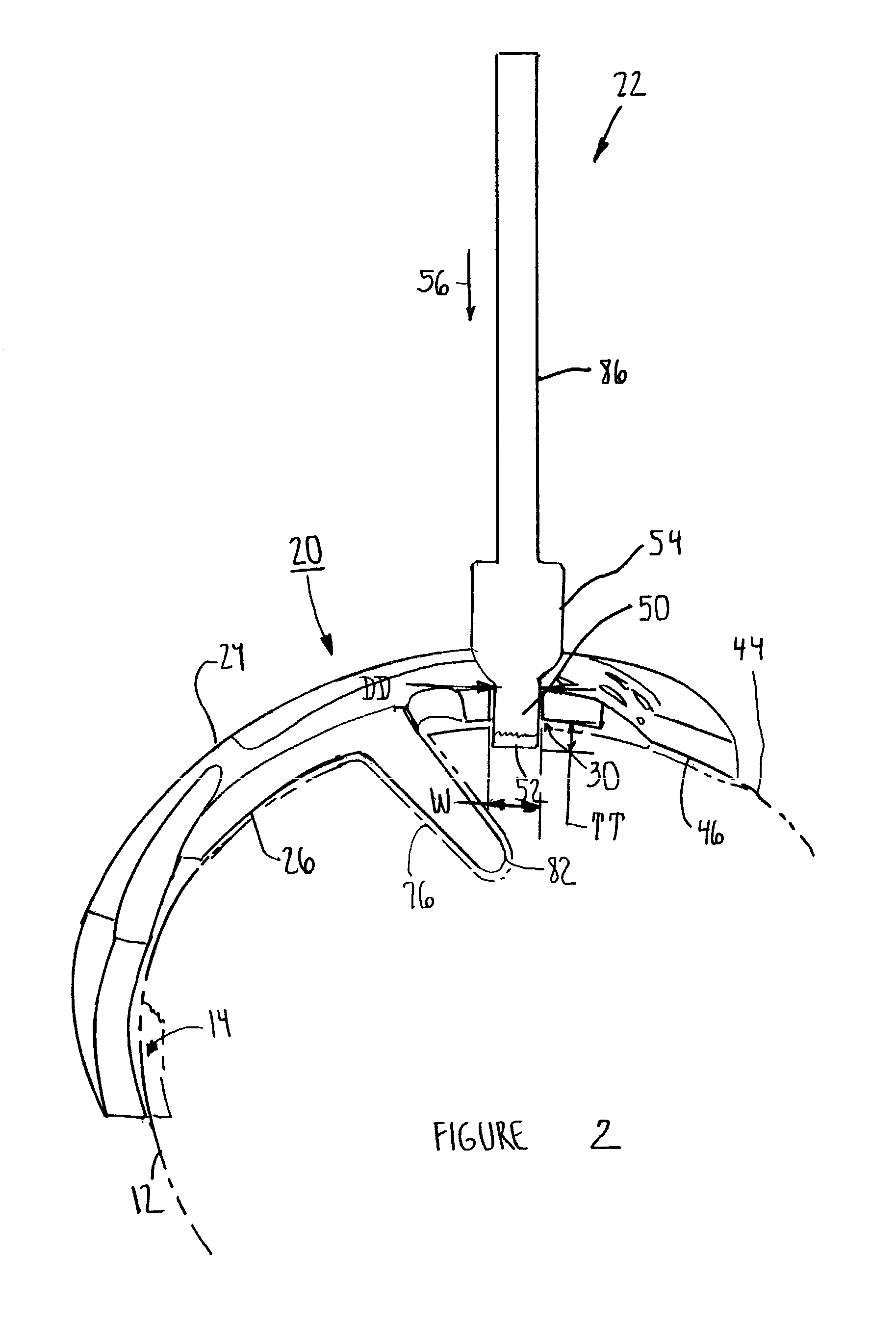
[0048]According to the present invention and referring now to FIG. 1, a kit 10 for removal of bone 12, for example, a portion of a long bone, from a patient to prepare a bone Cavity 14 for receiving a Joint prosthesis 16 (see FIGS. 11-14), is shown.

[0049]The kit 10 includes a guide 20 for cooperation with the long bone 12. The kit 10 also includes a Rotatable tool 22, which is constrained by the guide 20 for removal of the bone 12. The guide 20 includes a first portion 24 of the guide 20, which cooperates with the tool 22. The guide 20 further includes a second portion 26 of the guide 20, which cooperates with the long bone 12.

[0050]Preferably, and as shown in FIG. 1, the first portion 24 of the guide 20 defines a channel 30 through the guide 20. The tool 22 i...


PUM


Abstract

A kit (10) for removal of bone (12) from a patient to prepare a bone cavity (14) for receiving a joint prosthesis (16) is provided. The kit (10) includes a guide (20) for cooperation with the bone (12) and a rotatable tool (22). The tool (22) is constrainable by the guide (20) for removal of the bone (12). The guide (20) includes a first portion (24) thereof cooperable with the tool (22) and a second portion (24) thereof cooperable with the bone (12).

Description

CROSS-REFERENCE TO RELATED APPLICATIONS[0001]Cross reference is made to the following applications: U.S. patent application Ser. No. 10 / 177,966 entitled “PROSTHESIS CAVITY CUTTING GUIDE, CUTTING TOOL & METHOD” and U.S. patent application Ser. No. 10 / 176,934 entitled “PROSTHESIS REMOVAL CUTTING GUIDE, CUTTING TOOL AND METHOD” filed concurrently herewith which are incorporated herein by reference.TECHNICAL FIELD OF THE INVENTION[0002]The present invention relates generally to the field of orthopaedics, and more particularly, to an implant for use in arthroplasty.BACKGROUND OF THE INVENTION[0003]Joint replacement surgery is quite common and it enables many individuals to function properly when it would not otherwise be possible to do so. Such patients of joint replacement surgery typically suffer from osteoarthritis or rheumatoid arthritis. Artificial joints usually comprise metallic, ceramic and / or plastic components that are fixed to existing bone.[0004]Such joint replacement surgery...

Claims


Application Information

Patent Timeline
Patent Type & Authority Patents(United States)
IPC IPC(8): A61B17/60A61F2/00A61B17/16A61B17/17A61B19/00
CPCA61B17/1615A61B17/1675A61B17/1764A61B17/1742A61B2017/1602A61B2019/303A61B2017/1778A61B2090/033A61B17/1778
Inventor BROWN, SCOTTROGERS, JIMMERCHANT, ALAN C.
Owner DEPUY PROD INC
Why Eureka
Try Eureka