Electronic ballast with high power factor

a technology of electronic ballast and power factor, which is applied in the direction of lighting and heating apparatus, process and machine control, instruments, etc., can solve the problems of low cost, low power factor, and large circuit size, and achieve low cost, low cost, and low power factor. , to achieve the effect of reducing the current stress across the switch, reducing the cost of current generation, and reducing the loss of switching

Inactive Publication Date: 2012-07-03
JAIN PRAVEEN K +1
View PDF10 Cites 61 Cited by
  • Summary
  • Abstract
  • Description
  • Claims
  • Application Information

AI Technical Summary

Benefits of technology

[0016]Another aspect of the invention relates to a single-stage, single-switch electronic ballast topology using a single ended primary inductor converter (SEPIC) power factor corrector that is integrated with a single switch current fed inverter. An electronic ballast circuit as described herein is compact and minimizes components in the ballast power circuit. In one embodiment the switch is not connected in parallel with the resonant circuit, so the resonant current does not flow through the switch, resulting in lower current stress across the switch and lower switch conduction loss.

Problems solved by technology

However, this kind of circuit configuration usually results in a high cost.
Moreover, the large size of the circuit is incompatible with the size of a CFL.
Currently-available technology cannot achieve low cost, small size, high power factor, and dimmability in fluorescent lamps.

Method used


Image

  • Electronic ballast with high power factor
  • Electronic ballast with high power factor
  • Electronic ballast with high power factor

Examples


working examples

1. Electronic Ballast Circuit

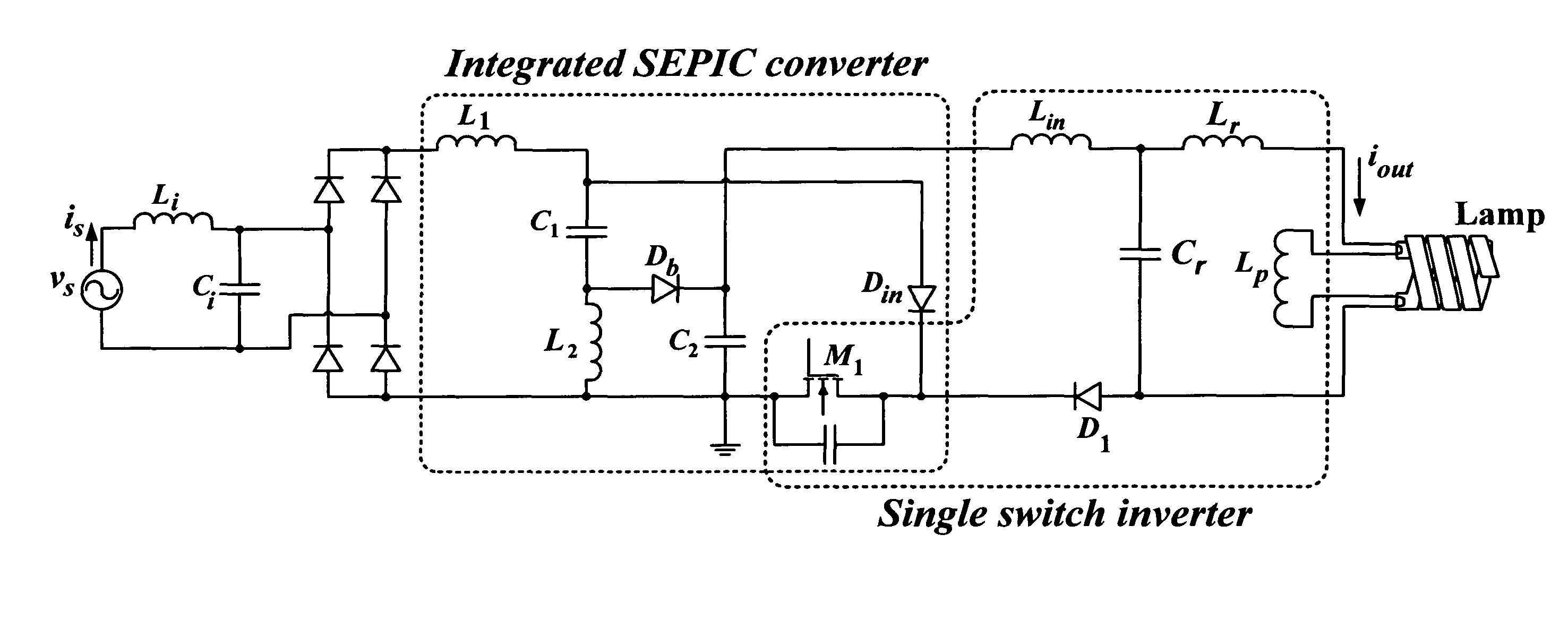
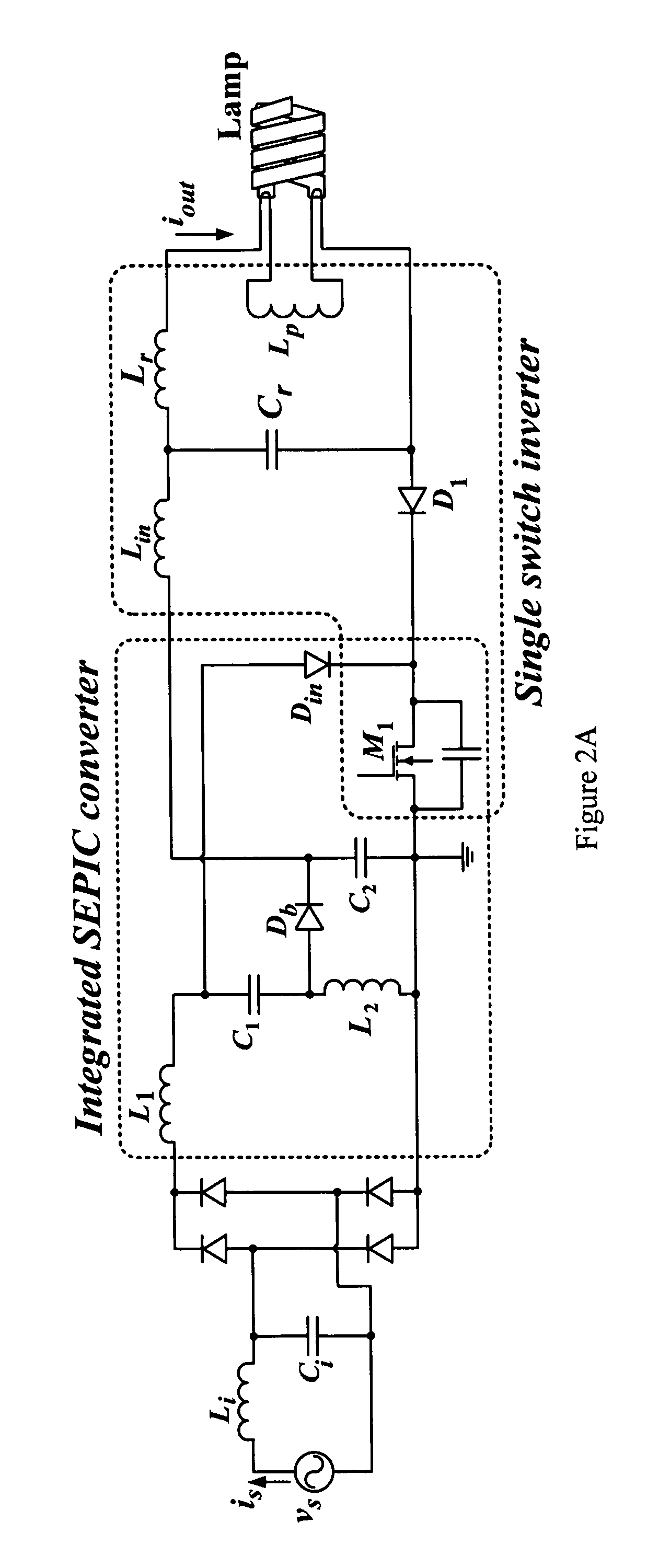
[0114]Performance of an electronic ballast circuit based on the embodiment of FIG. 2A was verified through simulation and an experimental prototype. A Sylvania Dulux® T / E 4-pin 26 W CFL with Iout=0.32 Arms was chosen as the testing load for the prototype with a line voltage of 110 Vrms 60 Hz. The switching frequency was 70 kHz and the quality factor was 2. The circuit parameters were calculated using the following steps:

(1): Rlamp was first calculated using Iout and Pout as shown in (14). Then the values of Lr, Cr and Lp were obtained using (3), (4) and (5) respectively.

[0115]Rlamp=PoutIout2=26⁢⁢W(0.32⁢⁢A)2≈250⁢Ω⁢⁢Lr=QRlamp2⁢π⁢⁢f2=2⁢(250⁢Ω)2⁢π⁡(70⁢⁢kHz)=1.1⁢⁢mH⁢⁢Cr=1(2⁢π⁢⁢fs)2⁢Lr=1(2⁢π⁢⁢70⁢⁢kHz)2⁢(1.1⁢⁢mH)=4.7⁢⁢nF(14)

Lp was selected to be higher than Lr so that sufficient high voltage would be guaranteed at the output during lamp ignition. In this example, Lp was selected to be 1.8 mH.

(2): Calculations of L1, L2, C2

[0116]The SEPIC inductors (L1 and L2) ...


PUM


Abstract

This invention provides an electronic ballast for a fluorescent lamp, including a rectifier for converting an alternating current input voltage into a direct current output voltage, and a circuit including a combined power factor correction (PFC) stage and an inverter, wherein the PFC stage and the inverter share a switch. Also provided is a controller for an electronic ballast, including a duty ratio controller that controls a duty ratio of a switch of the ballast, and means for adjusting the duty ratio according to a nonlinear function, so that an arc is sustained across the lamp. The controller and the ballast allow dimming of the fluorescent lamp while maintaining a high power factor.

Description

RELATED APPLICATIONS[0001]This application claims the benefit of the filing date of U.S. Provisional Patent Application No. 61 / 129,251, filed on 13 Jun. 2008, and of U.S. Provisional Patent Application No. 61 / 202,757, filed on 1 Apr. 2009, the contents of which are incorporated herein by reference in their entirety.FIELD OF THE INVENTION[0002]This invention relates to an electronic ballast for a fluorescent lamp, and to a dimmer controller for a an electronic ballast. In particular, this invention relates to an electronic ballast and a dimmer controller with high power factor and compact size, suitable for a compact fluorescent lamp.BACKGROUND OF THE INVENTION[0003]Fluorescent lighting is widely used in residential and commercial applications. Because a fluorescent lamp consumes only one-third of the power that is dissipated in an incandescent lamp of equivalent light output, and its lifetime is 1000 times that of an incandescent lamp [1], it conserves energy and reduces the energy ...

Claims


Application Information

Patent Timeline
Patent Type & Authority Patents(United States)
IPC IPC(8): H05B41/16
CPCH05B41/28H05B41/2822H05B41/3927Y02B20/19Y02B20/00
Inventor LAM, JOHNJAIN, PRAVEEN
Owner JAIN PRAVEEN K
Why Eureka
Try Eureka