Surface wave coupler

a surface wave and coupler technology, applied in waveguides, frequency-division multiplexes, instruments, etc., can solve the problems of carrier signal interference, signal may not be able to adequately penetrate a building structure to reach the wireless receiver inside,

Active Publication Date: 2012-07-03
AT&T INTPROP I LP
View PDF6 Cites 669 Cited by
  • Summary
  • Abstract
  • Description
  • Claims
  • Application Information

AI Technical Summary

Problems solved by technology

Disadvantageously, such signals may not be able to adequately penetrate a building structure to reach wireless receivers inside, particularly when the transmitter is mounted on a building foundation—the composition and thickness of which can present a major impediment to the transmission of the low power signal into the structure, and even more so when the foundation contains reinforcement bars or other metallic elements.
However, such a power increase might cause the carrier signal to interfere with like signals generated by transmitters at other buildings nearby.

Method used


Image

  • Surface wave coupler
  • Surface wave coupler
  • Surface wave coupler

Examples


Embodiment Construction

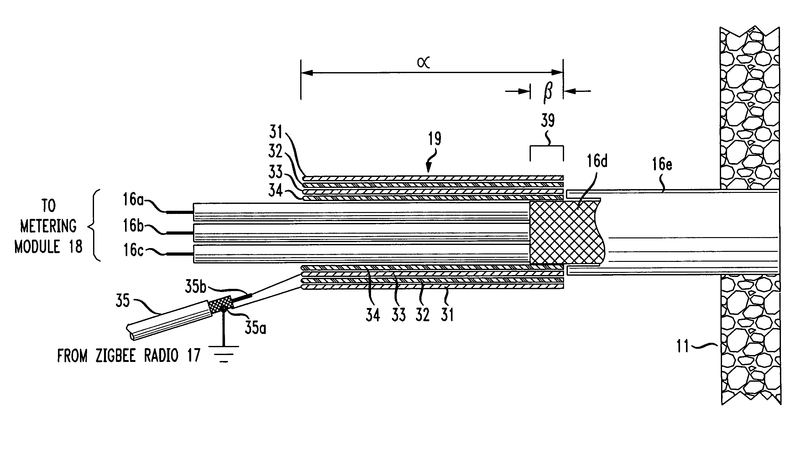
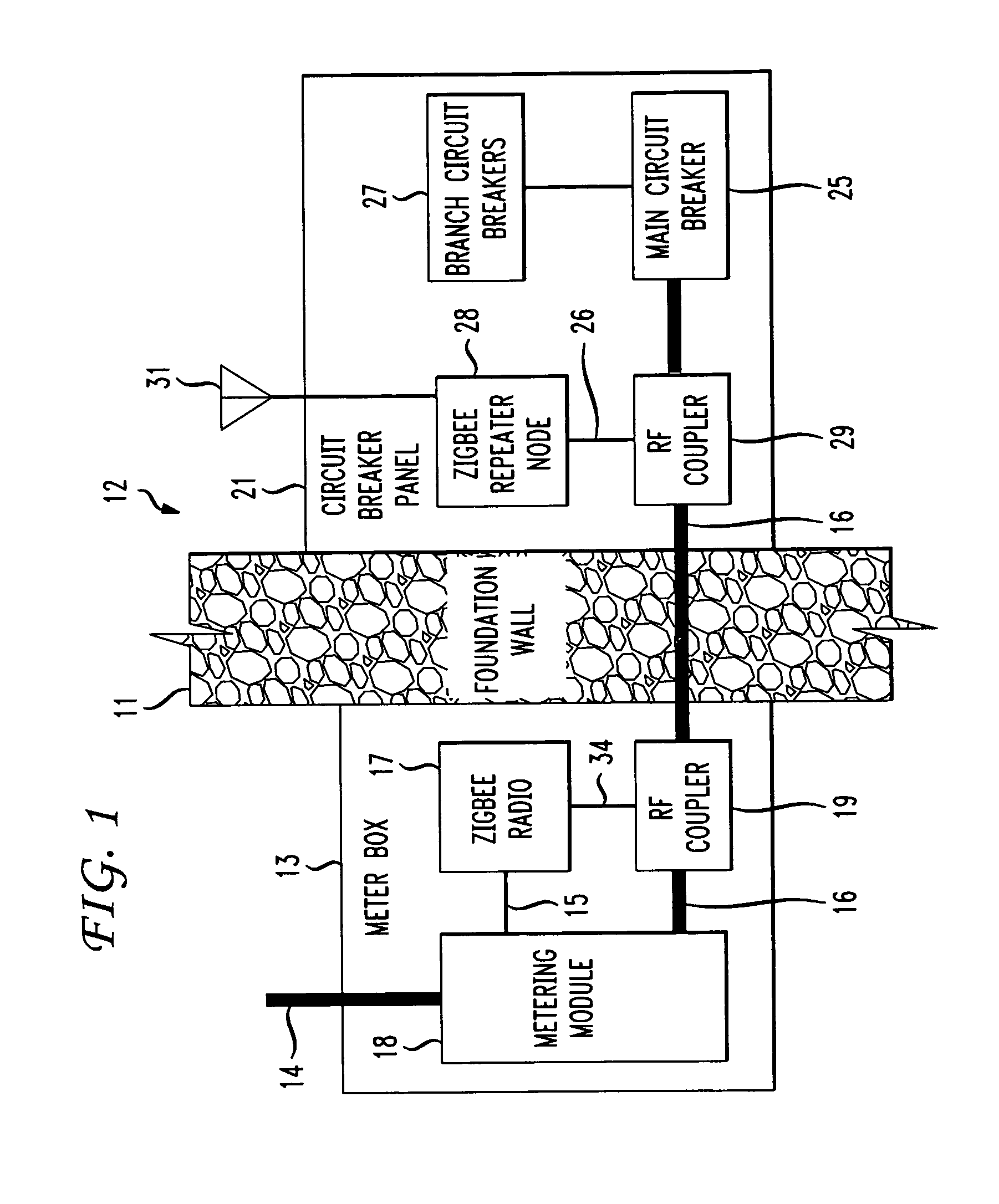
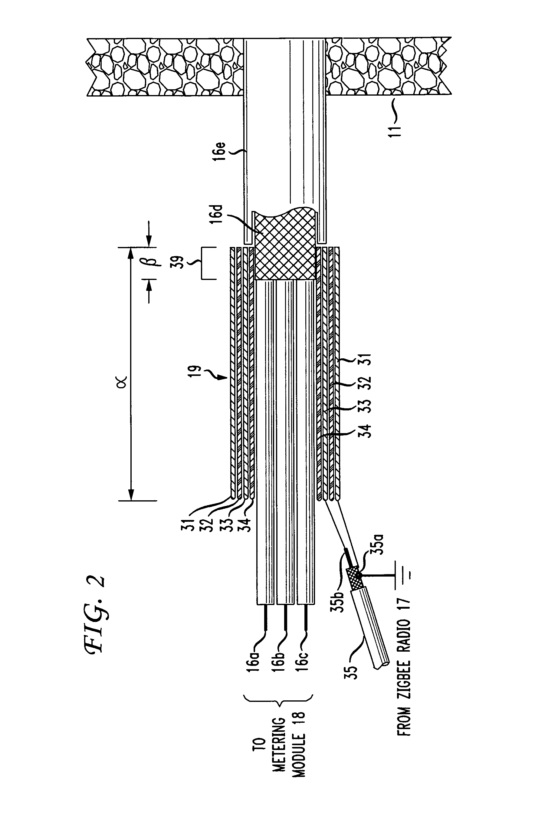
[0008]FIG. 1 shows a portion of a foundation wall 11 of a building or other structure, having an interior area denoted as 12. Attached to the exterior side of foundation wall 11 is a meter box 13 into which comes a service entrance cable 14 carrying derives power from, say, a utility pole near the building via a so-called “drop” and a service-entrance cable that terminates at meter box 13. Service entrance cable 14 terminates on a watt-hour meter (not shown) within a metering module 18 which is, in turn, mounted within meter box 13. A service cable 16 connected to (typically) the base of the watt-hour meter extends through foundation wall 11 supplies electrical power to main circuit breaker 25 mounted on circuit breaker panel 21 mounted on the interior side of foundation wall 11. Main circuit breaker 25 supplies power to individual branch circuit breakers 27 which, in turn, supply power to outlets, fixtures and appliances via 15- or 20-ampere circuits comprising 12 AWG or 14 AWG con...


PUM


Abstract

The RF signal generated by a ZigBee radio on the outside of a building structure is conveyed to the interior of the building by guiding it along an electric cable bundle that passes through the building's wall to supply domestic electric power to the interior of the structure. The RF signal is launched by a unique coupler comprising a pair of insulated foil conductors.

Description

BACKGROUND[0001]Arrangements are known for automatic / remote reading of utility meters, and it is known that the so-called “ZigBee” (IEEE standard 802.15.4) wireless network interface has gained favor for such applications. A metering module within the meter box affixed to the outside of the building served by the utility service in question, e.g., electric power, obtains the current utility meter reading (hereinafter “utility meter data”) and applies it to a ZigBee radio, which modulates the meter reading onto a carrier signal conforming to the ZigBee wireless networking standard. The carrier signal is transmitted over the air to a neighborhood “aggregator node” and then through wired or cellular backhaul facilities to the utility company.[0002]Concurrent with these developments, there has been an increased interest by utility customers in being able to obtain utility meter data on an ongoing basis in order to monitor electric or other utility usage as part of an energy conservation...

Claims


Application Information

Patent Timeline
Patent Type & Authority Patents(United States)
IPC IPC(8): H01P3/10H01P5/18H04B3/56
CPCH01P3/06H01P5/12
Inventor MILLER, II, ROBERT R.WORSTELL, HARRY R.
Owner AT&T INTPROP I LP
Why Eureka
Try Eureka