Device and method for the determination of distance by means of light pulses

a technology of light pulses and devices, applied in distance measurement, surveying and navigation, instruments, etc., can solve the problems of increasing the travel time of light pulses, decreasing the maximum light pulse frequency, and affecting the accuracy of distance measurement results

Active Publication Date: 2012-07-03
TRIMBLE GERMANY
View PDF13 Cites 17 Cited by
  • Summary
  • Abstract
  • Description
  • Claims
  • Application Information

AI Technical Summary

Benefits of technology

[0014]The above design makes it possible for the at least two timers to measure in each case independently of each other, within a short temporal interval, the light travel time of light pulses, so that several light pulses can be present simultaneously in the air, i.e., on the path between the light source, the reflection site, and the detector.

Problems solved by technology

In the process, the problem that arises is that with increasing distance of the aviation-supported LIDAR device from the site of the reflection, the maximum light pulse frequency, i.e., the frequency at which the light pulses can be emitted by the LIDAR device, decreases necessarily, because the travel time of the light pulses increases with increasing distance.

Method used


Image

  • Device and method for the determination of distance by means of light pulses
  • Device and method for the determination of distance by means of light pulses
  • Device and method for the determination of distance by means of light pulses

Examples


Embodiment Construction

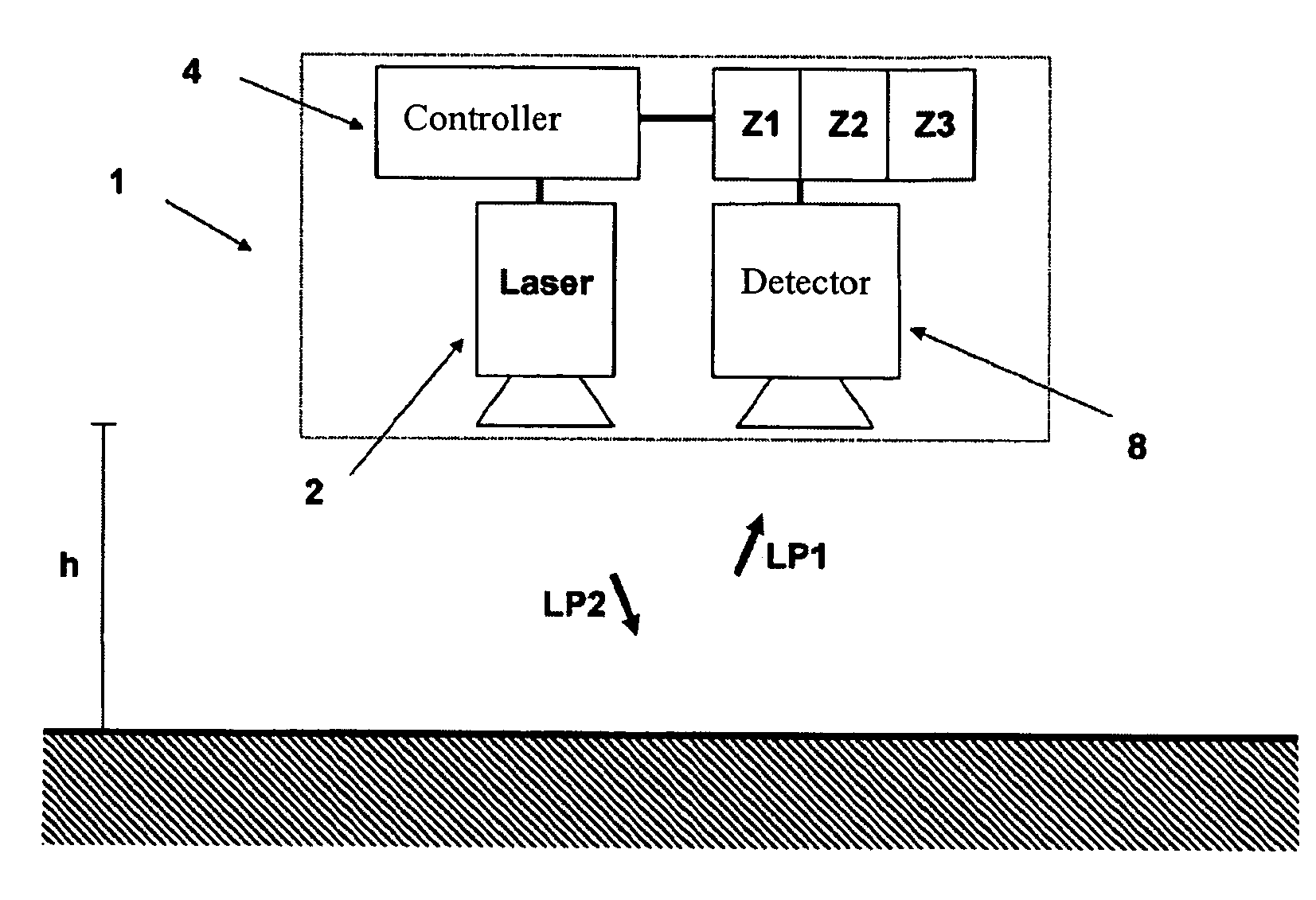
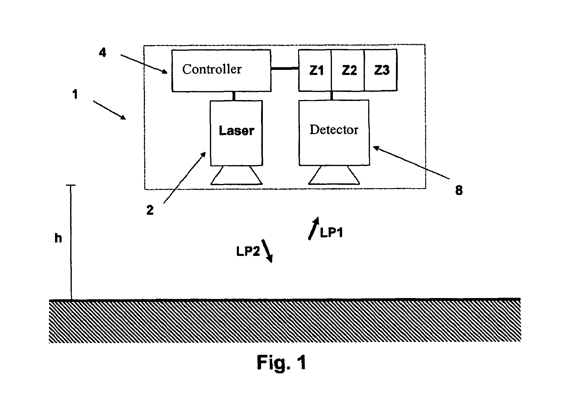
[0030]FIG. 1 is a schematic representation of a device 1 according to the invention for the determination of distance by means of light pulses. This device can be installed, for example, in an aircraft, in order to carry out, at a flying altitude of h, distance measurements, and thus acquire data on the terrain being flown over. The device 1 for the determination of distance by means of light pulses comprises a light source (for example, a laser) 2 for the emission of light pulses with a certain frequency. The light pulses emitted and reflected by the light source 2 (for example LP1 and LP2) are received by a detector 8. The detector 8 and the light source 2 are connected to a controller 4, which is in communication with them or can control them.

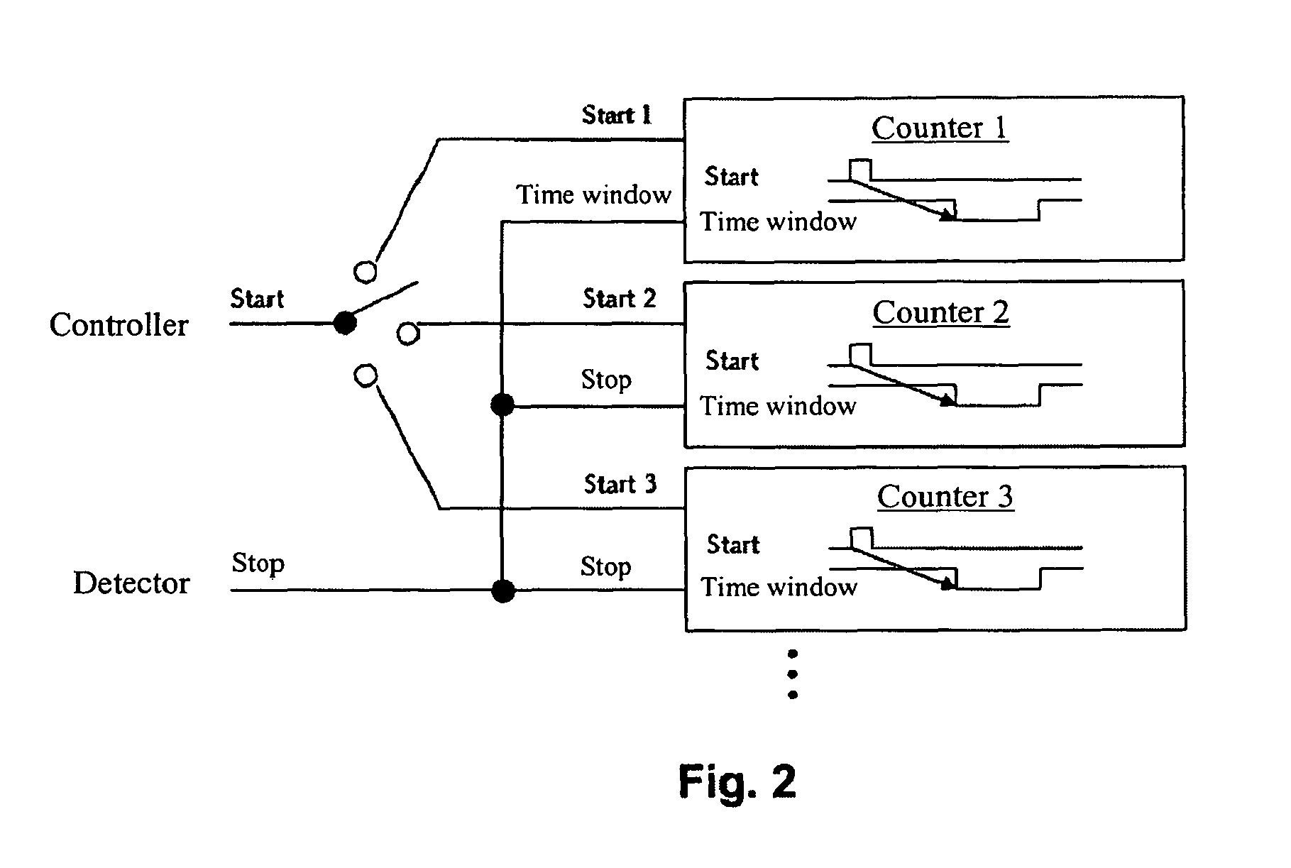
[0031]As one can now also see in FIGS. 2 and 3, the device 1 according to the invention for the determination of distance by means of light pulses comprises furthermore several timers or counters (in FIGS. 1 to 3, three counters or timers Z1...


PUM


Abstract

A device (1) for the determination of distance by means of light pulses is disclosed. The device (1) comprises a light source (2) for emitting light pulses with a specified frequency, a detector (8) for receiving the light pulses emitted and reflected by the light source, and a controller (4) which is in communication with the light source (2) and the detector (8) and which can control said light source and detector by means of signals. The device (1) further comprises at least two timers (Z1, Z2, Z3) which are connected to the controller (4) and the detector (8). Said controller (4) is designed in such a way that when a light pulse is emitted by the light source (2), the controller (4) generates a start signal which triggers the time measurement by each one of the at least two timers, in order, and beginning again from the start. The detector (8) is designed in such a way that upon receiving a reflected light pulse, said detector (8) generates a stop signal which is forwarded to the at least two timers (Z1, Z2, Z3) and which stops the time measurement by the timer of the at least two timers, to which at that instant a measuring window is assigned by the controller (4). The device can preferably be designed as a fiber-optic scanner. In addition, a method for the determination of distance by means of light pulses is disclosed.

Description

RELATED APPLICATIONS[0001]This application claims benefit of German application for patent DE 10 2007 010 236.6 filed 2 Mar. 2007, the content of which is incorporated herein by this reference, and of International application for patent PCT / EP2008 / 001628 filed 29 Feb. 2008, the content of which is incorporated herein by this reference.FIELD OF THE INVENTION[0002]The invention relates to a device and a method for the determination of distance by means of light pulses. The invention relates particularly to a LIDAR device and a LIDAR method.BACKGROUND OF THE INVENTION[0003]Aviation-assisted devices for the determination of distance by means of light pulses are used particularly for the measurement of data before the establishment of digital terrain models, where the distance to the site of the reflection is determined from the travel time of the light pulse from the device to the site of the reflection and again back to the device (i.e., the light echo).[0004]Such devices and methods ...

Claims


Application Information

Patent Timeline
Patent Type & Authority Patents(United States)
IPC IPC(8): G01C3/08G01S17/18
CPCG01S7/4817G01S17/107G01S7/4818G01S7/497G01S17/18
Inventor RINDLE, PETER
Owner TRIMBLE GERMANY
Why Eureka
Try Eureka