Method and apparatus for reviewing defects on mask

a mask and defect technology, applied in the field of mask defects review methods and apparatus, can solve the problems of masks that need to be defectless, take a long time to complete the review, and generate pseudo defects, etc., and achieve the effect of reducing the review tim

Active Publication Date: 2012-07-03
NUFLARE TECH INC
View PDF9 Cites 6 Cited by
  • Summary
  • Abstract
  • Description
  • Claims
  • Application Information

AI Technical Summary

Benefits of technology

[0012]It is, therefore, an object of the present invention to provide a method and apparatus which are capable of reducing a review time for reviewing defects on a mask.

Problems solved by technology

Thus, the mask needs to be defectless.
Therefore, a defect detected by the die-to-die inspection also is included in defects detected by comparing the standard image with the other optical image.
The pseudo defect may be generated due to malfunctioning of the mask inspection apparatus, distortion on the surface of the mask, or a variation in an environment (temperature, humidity, atmospheric pressure, etc.) during the inspection of the mask.
Thus, it takes much time to complete the review.

Method used


Image

  • Method and apparatus for reviewing defects on mask
  • Method and apparatus for reviewing defects on mask
  • Method and apparatus for reviewing defects on mask

Examples


Embodiment Construction

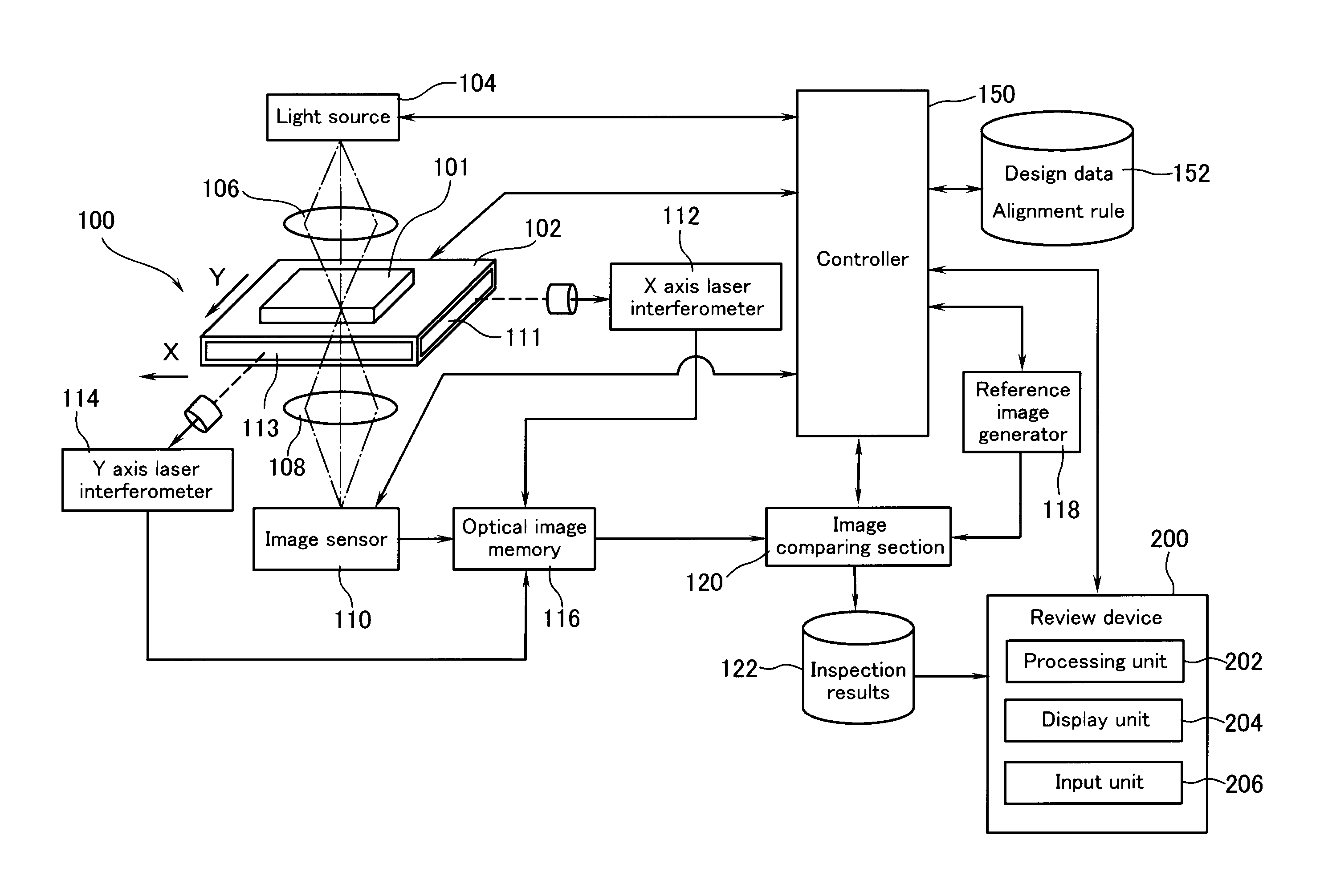
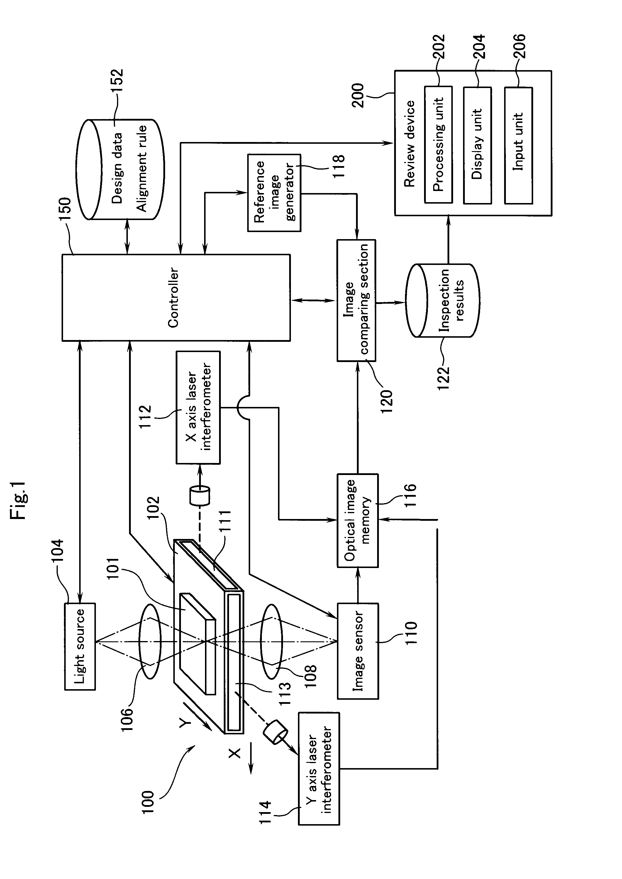
[0030]FIG. 1 is an outline diagram showing the configuration of a mask inspection apparatus 100 according to an embodiment of the present invention. The mask inspection apparatus 100 has a stage 102 for holding a mask 101 that is to be inspected.

[0031]The stage 102 can be driven by a motor (not shown) in an X direction and a Y direction. A controller 150 controls and drives the stage 102. The controller 150 performs entire control related to an inspection of a mask.

[0032]A mirror 111 is provided on a side surface of the stage 102, and the side surface being parallel to the Y direction. A mirror 113 is provided on another side surface of the stage, and the side surface being parallel to the X direction. An X axis laser interferometer 112 facing the mirror 111, and a Y axis laser interferometer 113 facing the mirror 113 are provided.

[0033]The X axis laser interferometers 112, 114 emit laser beams to the mirror 111, 113 and receive lights reflected on the mirror 111, 113, respectively....


PUM


Abstract

A defect to be reviewed is selected from a plurality of defects obtained from inspection results. When the selected defect is a defect of a pattern written using an iteration expression in design data on the mask, another pattern written using the iteration expression in the design data is extracted. A defect present in another pattern is extracted. A peripheral pattern portion located at the periphery of the selected defect and a peripheral pattern portion located at the periphery of the extracted defect are extracted. It is determined whether the peripheral pattern portions extracted are similar to each other. When the peripheral pattern portions are similar to each other, the selected defect and the extracted defect are grouped. It is determined whether the selected defect is an actual defect or a pseudo defect. The determination result is applied to the other grouped defect.

Description

BACKGROUND OF THE INVENTION[0001]1. Field of the Invention[0002]The present invention relates to a method and apparatus for reviewing defects on a mask.[0003]2. Background Art[0004]In a process for manufacturing a semiconductor device, a reticle or photomask (hereinafter referred to as a mask) is used to form a circuit pattern on a wafer. When the mask has a defect, the defect is transferred to the circuit pattern. Thus, the mask needs to be defectless. In response to such needs, defects on a formed mask are inspected by comparing an optical image of the mask with a standard image.[0005]A die-to-die inspection and a die-to-database inspection are known in the art as a method for inspecting defects on a mask. In the die-to-die inspection, an optical image of a pattern that is written on a region of a mask and has a certain shape is compared with an optical image of a pattern that is written on another region of the mask and has the same shape. In this case, one of the optical images ...

Claims


Application Information

Patent Timeline
Patent Type & Authority Patents(United States)
IPC IPC(8): G06K9/00
CPCG06T7/001G06T2207/30148
Inventor INOUE, TAKAFUMISUGINO, MASANORI
Owner NUFLARE TECH INC
Why Eureka
Try Eureka