
Developing device removably mountable in an image forming apparatus, and image forming apparatus having the same

a development device and image forming technology, applied in the field of image forming apparatus, can solve the problems of increasing the difficulty of compactly manufacturing the image forming apparatus, stably restraining the vibration the large range of the developing device, so as to reduce the possibility of damage to components, improve the handling convenience of mounting, and remove the developing device

Active Publication Date: 2012-07-03
HEWLETT PACKARD DEV CO LP
View PDF12 Cites 6 Cited by
  • Summary
  • Abstract
  • Description
  • Claims
  • Application Information

AI Technical Summary

Benefits of technology

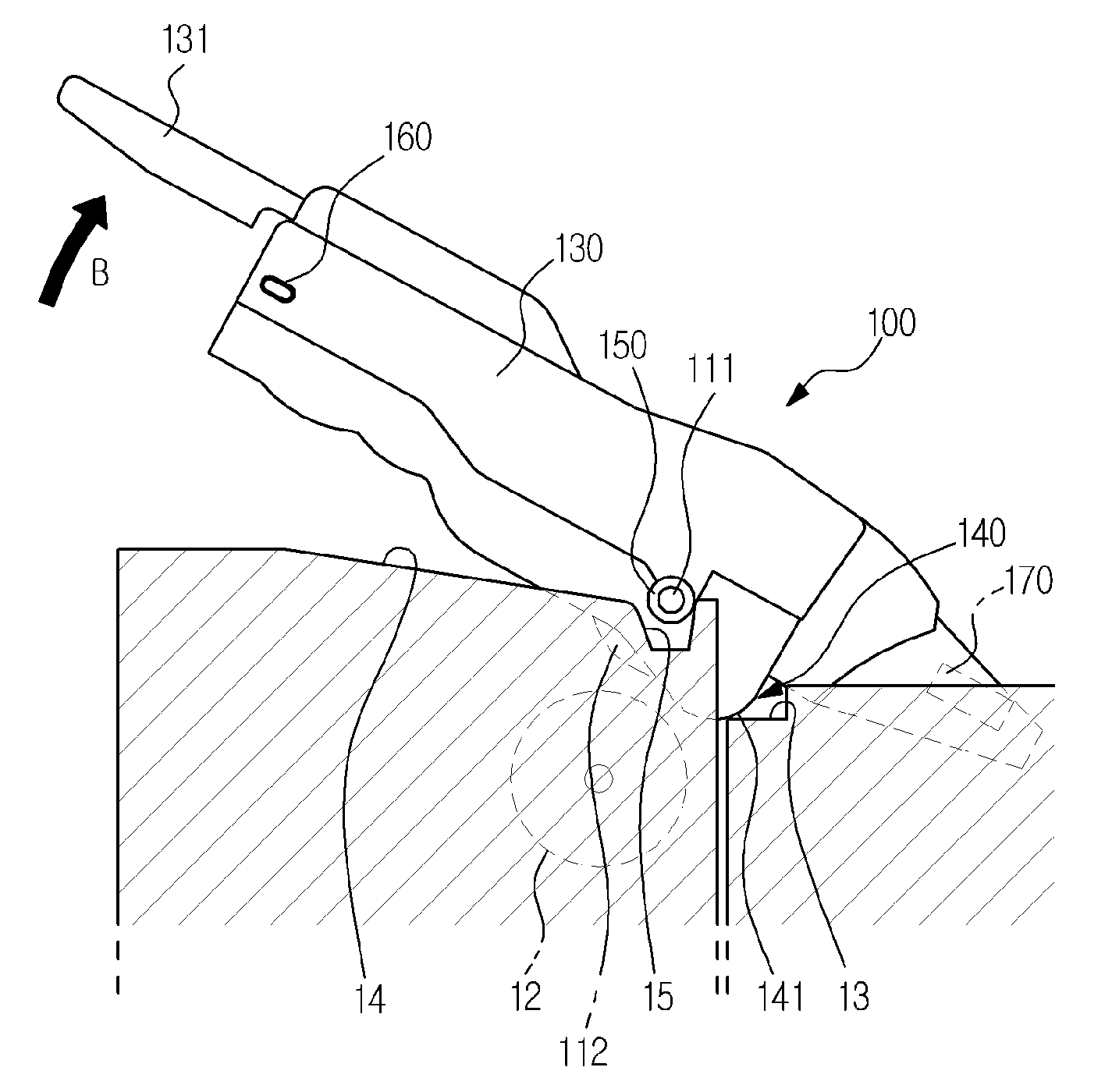
[0018]It is another aspect of the invention to have a developing device and an image forming apparatus having the same, which improves handling convenience in mounting and removing the developing device.
[0019]It is yet another aspect of the invention to have a developing device and an image forming apparatus having the same, which reduces possibility of damages to components mounted on an upper surface of the developing device when the developing device is removed from a main body of the image forming apparatus.

Problems solved by technology

However, when the above described developing device of U.S. Pat. No. 5,937,240 rotates on the second protrusion, the moving range of the developing device is large.
Thus, the above described developing device requires a large surrounding space for movement.
Thus, a size of the image forming apparatus is increased to provide sufficient space for movement of the developing device in the center portion in the main body, which makes it difficult to compactly manufacture the image forming apparatus.
However, to aid the removal of the developing device from the main body, if the pressing force of the press device is set to be relatively lower in consideration of handling convenience, stably restraining the vibration of the developing device becomes more difficult.
Conversely, if the pressing force of the press device is set to be relatively higher, handling convenience is deteriorated as removal of the developing device from the main body becomes more difficult.
However, when the developing device is rotated upward in order to be removed from the main body, the components mounted on the upper surface of the developing device may be damaged by forced contact with the components mounted in the main body.

Method used


Image

  • Developing device removably mountable in an image forming apparatus, and image forming apparatus having the same
  • Developing device removably mountable in an image forming apparatus, and image forming apparatus having the same
  • Developing device removably mountable in an image forming apparatus, and image forming apparatus having the same

Examples


Embodiment Construction

[0044]Reference will now be made in detail to aspects of the present invention, examples of which are illustrated in the accompanying drawings, wherein like reference numerals refer to like elements throughout. The aspects are described below in order to explain the present invention by referring to the figures.

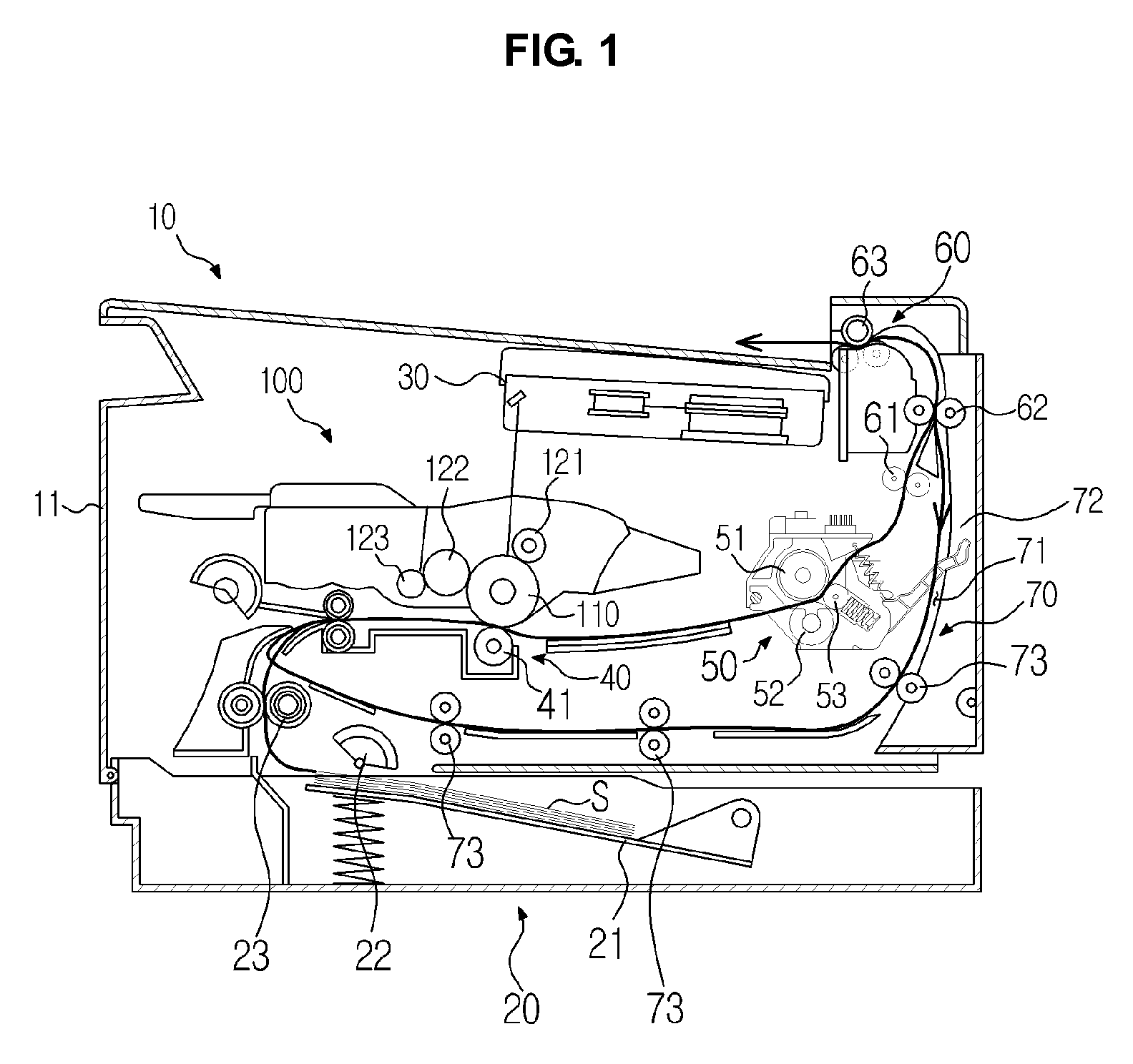
[0045]FIG. 1 is a sectional view illustrating various components of an image forming apparatus according to an aspect of the present invention. As shown in FIG. 1, an image forming apparatus includes a main body 10, which forms an external shape of the image forming apparatus and supports the various components accommodated therein. Inside the main body 10 are mounted a feeding device 20, a laser scanning device 30, a developing device 100, a transfer device 40, a fusing device 50, a discharge device 60, and a duplex printing device 70.

[0046]The main body 10 also includes a cover 11 that is hingedly coupled to the main body 10 to reveal or cover an opening of the main body 10...


PUM


Abstract

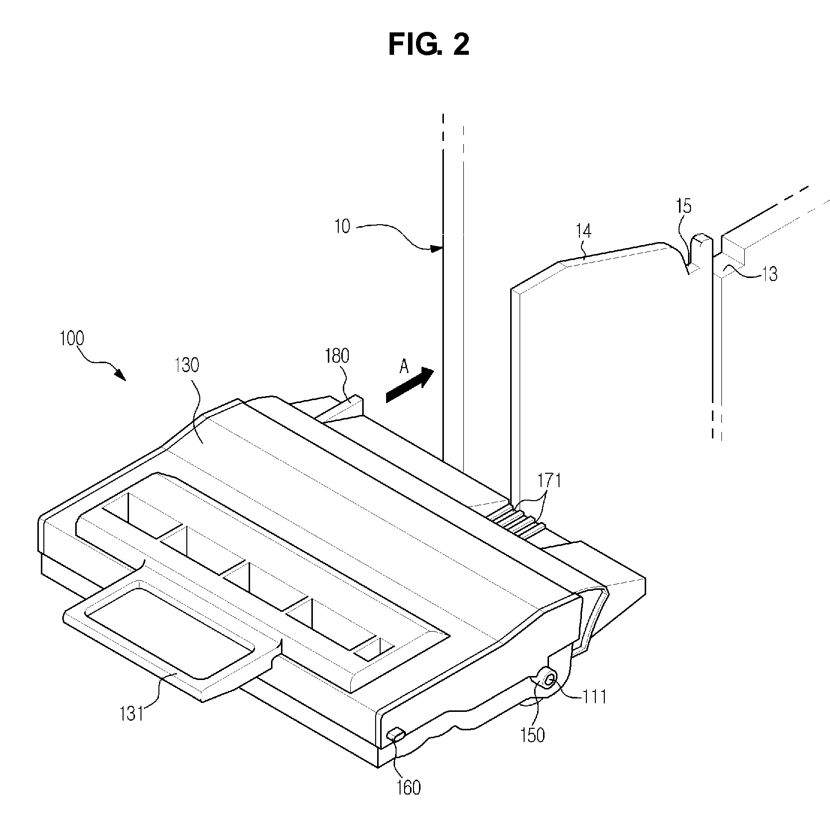
A developing device and an image forming apparatus having the same include a frame having a knob part, a photosensitive body provided in front of the knob part with respect to a first direction of mounting the developing device, and a rotation guide part provided in front of the photosensitive body with respect to the first direction, and to guide a rotational motion of the developing device. When the developing device is removed from the image forming apparatus, the knob part is rotated upward. A first protrusion is provided on a side surface of the frame to determine a mounting position of the developing device. When the knob part is rotated upward, the first protrusion is rotated in the same direction as the knob part. Accordingly, the developing device has an improved mounting / removing structure adequate to compactly manufacture the image forming apparatus, and improves handling convenience in mounting and removing the developing device.

Description

CROSS-REFERENCE TO RELATED APPLICATION[0001]This application claims the benefit of Korean Patent Application No. 2007-95069, filed Sep. 19, 2007 in the Korean Intellectual Property Office, the disclosure of which is incorporated herein by reference.BACKGROUND OF THE INVENTION[0002]1. Field of the Invention[0003]Aspects of the present invention relate to an image forming apparatus, and more particularly, to a developing device removably mounted in a main body of the image forming apparatus, and an image forming apparatus having the developing device.[0004]2. Description of the Related Art[0005]An image forming apparatus, such as a printer, a copying machine, or a fax machine, forms an image on a printing medium according to an inputted image signal. Of the various types of image forming apparatuses, an electrophotographic image forming apparatus prints an image on the printing medium, such as paper, through feeding, developing, transferring, fusing, and discharging processes.[0006]An...

Claims


Application Information

Patent Timeline
Patent Type & Authority Patents(United States)
IPC IPC(8): G03G21/16
CPCG03G21/1853G03G2221/1846G03G2221/1884G03G15/00G03G15/06
Inventor CHOI, JAI ILKIM, YOUNG MIN
Owner HEWLETT PACKARD DEV CO LP
Learn More