
Quantizing a joint-channel-encoded audio signal

a technology of audio signal and quantization, applied in the field of quantizing jointchannel encoded audio signals, can solve the problems of significant audible distortion, poor frequency resolution cost of good frequency resolution, and increased frequency resolution cost proportionately poor, so as to achieve efficient and accurate encoding of a given audio signal and good frequency resolution

Active Publication Date: 2012-07-03
DIGITAL RISE TECH CO LTD
View PDF4 Cites 2 Cited by
  • Summary
  • Abstract
  • Description
  • Claims
  • Application Information

AI Technical Summary

Benefits of technology

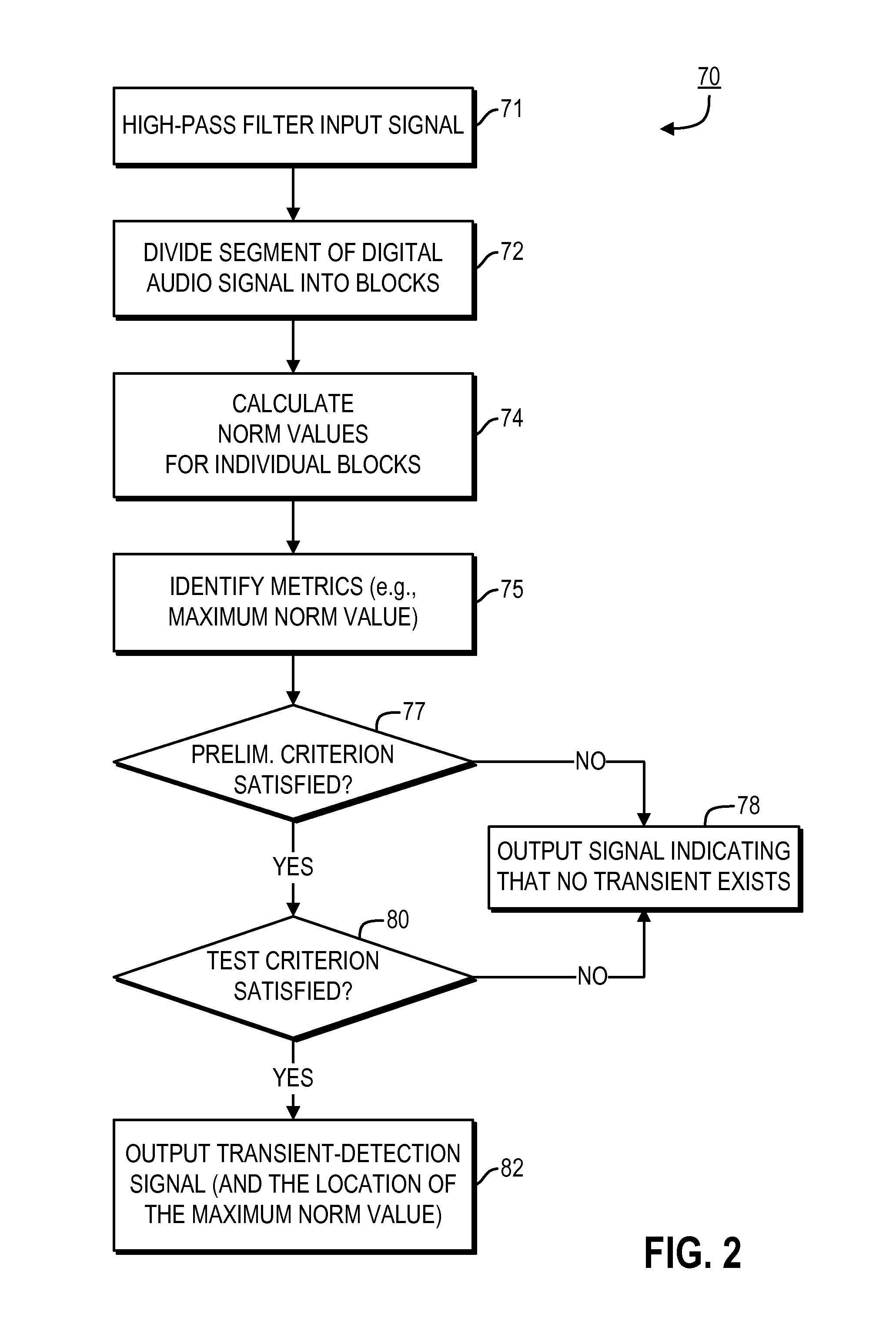
"The present invention provides a method for detecting transients in audio signals by comparing maximum block norm values to a second maximum block norm value within a desired segment using a multi-stage technique or multiple different criteria based on norm values of signal blocks. This allows for more accurate detection of transients in audio signals."

Problems solved by technology

However, as is well known, the cost of good frequency resolution is poor time resolution.
While that result is acceptable for a quasi-stationary portion of the signal, applying a long transform to a portion of an audio signal that includes a transient essentially would spread the transient's energy over the entire transform interval, thereby resulting in significant audible distortion.
Of course, the cost of such increased time resolution is proportionately poorer frequency resolution.
However, good frequency resolution typically is not as important when reproducing a transient, because human audio perception is not as sensitive over such a short period of time.
However, each of such approaches has its own limitations.

Method used


Image

  • Quantizing a joint-channel-encoded audio signal
  • Quantizing a joint-channel-encoded audio signal
  • Quantizing a joint-channel-encoded audio signal

Examples


Embodiment Construction

)

[0023]The present disclosure is divided into sections. The first section describes audio signal transient detection. The second section describes codebook merging. The third section describes joint channel coding.

Audio Signal Transient Detection

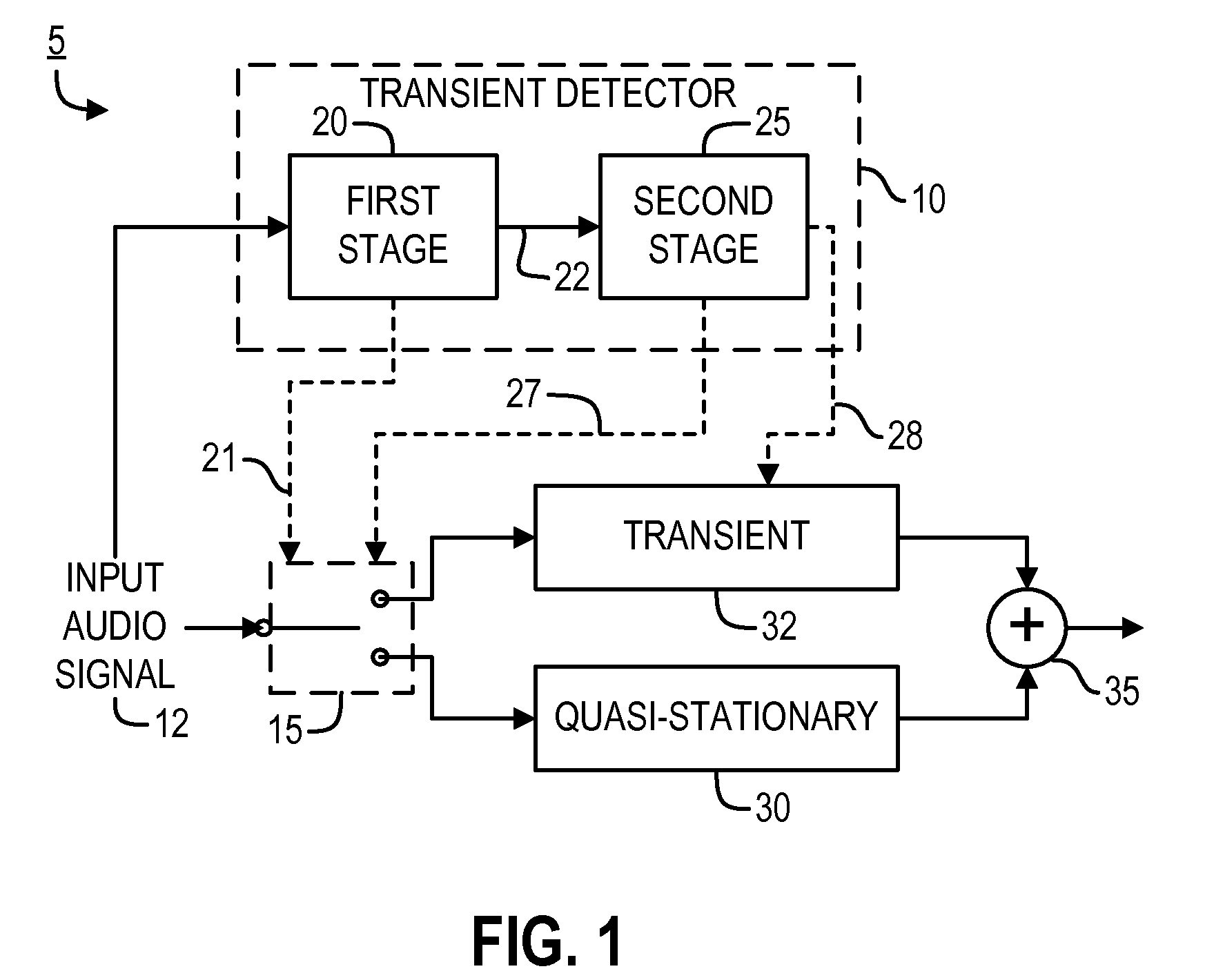
[0024]FIG. 1 illustrates an exemplary system 5 within which might operate a transient-detection system or technique 10 (referred to herein as transient detector 10) according to a representative embodiment of the present invention. As shown in FIG. 1, an input audio signal 12 preferably is provided to two components of system 5: the transient detector 10 and processing switch 15. In the preferred embodiments of the invention transient detector 10 includes a first processing stage 20 and a second processing stage 25, and the input audio signal 12 initially is provided to the first stage 20. However, it should be noted that transient detector 10 instead might include a single processing stage that includes any or all of the processing discusse...


PUM


Abstract

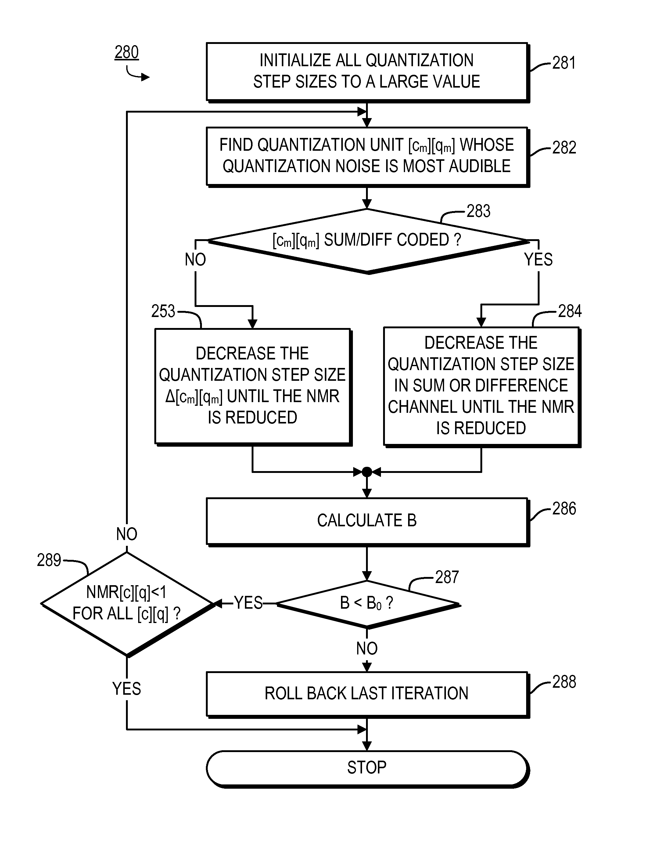
Provided are, among other things, systems, methods and techniques for quantizing a joint-channel-encoded audio signal, e.g., by: identifying a target quantization unit for reduction of quantization step size based on quantization errors; determining whether the target quantization unit has been jointly sum / difference encoded with another quantization unit; if the target quantization unit has been jointly sum / difference encoded with another quantization unit, then (i) designating the sum or difference channel quantization unit as a target S / D quantization unit in based on which has a greater quantization error and (ii) re-quantizing the target S / D channel quantization using a decreased quantization step size; recalculating the quantization error for the target quantization unit; and repeating the process until a specified criterion is satisfied.

Description

[0001]This application is a continuation of U.S. patent application Ser. No. 12 / 129,913, filed on May 30, 2008, and titled “Audio Signal Transient Detection”, which application is incorporated by reference herein as though set forth herein in full. The Background and Summary of the presently claimed invention mainly can be found in the initial paragraphs of the section below titled “Joint Channel Coding”.FIELD OF THE INVENTION[0002]The present invention pertains to systems, methods and techniques for quantizing joint-channel-encoded audio signals.BACKGROUND[0003]Generally speaking, within the timeframes in which audio signal processing occurs, most of a typical audio signal is quasi-stationary in nature, meaning that its statistics (e.g., in the frequency domain) change relatively slowly. However, it is also fairly common for such quasi-stationary portions to be punctuated and / or separated by transients. A transient can be defined in a variety of different ways, but generally it is ...

Claims


Application Information

Patent Timeline
Patent Type & Authority Patents(United States)
IPC IPC(8): G10L19/00
CPCG10L19/00G10L19/025G10L19/265G10L19/002G10L19/032G10L2019/0001
Inventor YOU, YULI
Owner DIGITAL RISE TECH CO LTD
Learn More