Trench compacting apparatus

a technology of compacting wheel and trench wall, which is applied in the direction of agricultural rollers, soil preservation, applications, etc., can solve the problems of reducing affecting the work efficiency of the operator, and having to be supervised by the operator. , to achieve the effect of enhancing the compaction effect and increasing the working width

Inactive Publication Date: 2012-07-10
ARMAGH (VIC) PTY LTD
View PDF28 Cites 3 Cited by
  • Summary
  • Abstract
  • Description
  • Claims
  • Application Information

AI Technical Summary

Benefits of technology

[0018]In another embodiment, for ease of fitting, the multi-foot pad has locating surfaces that, when the multi-foot pad is placed on the wheel assembly for securing thereto, bear against the wheel assembly so as to correctly position the feet radially and / or axially on the rim portion of the wheel assembly. This arrangement may be particularly convenient when the multi-foot pad is to be secured by welding.
[0022]At least one of the wheel assemblies may include an endmost wheel assembly that may be secured to an outermost wheel assembly of the device to increase its working width.
[0023]In another embodiment, the compaction device or the machine to which it is mounted may be provided with means for vibrating the wheel assemblies to enhance the compaction effect where required.

Problems solved by technology

Compacting devices that comprise a single drum with feet projecting therefrom and which is supported for rotation between fork arms can lead to difficulties in compacting soil adjacent the walls of a trench.
However, devices of this type, have their own problems.
This can be a time consuming process that requires significant operator skill in manoeuvring the machine.

Method used


Image

  • Trench compacting apparatus
  • Trench compacting apparatus
  • Trench compacting apparatus

Examples


Embodiment Construction

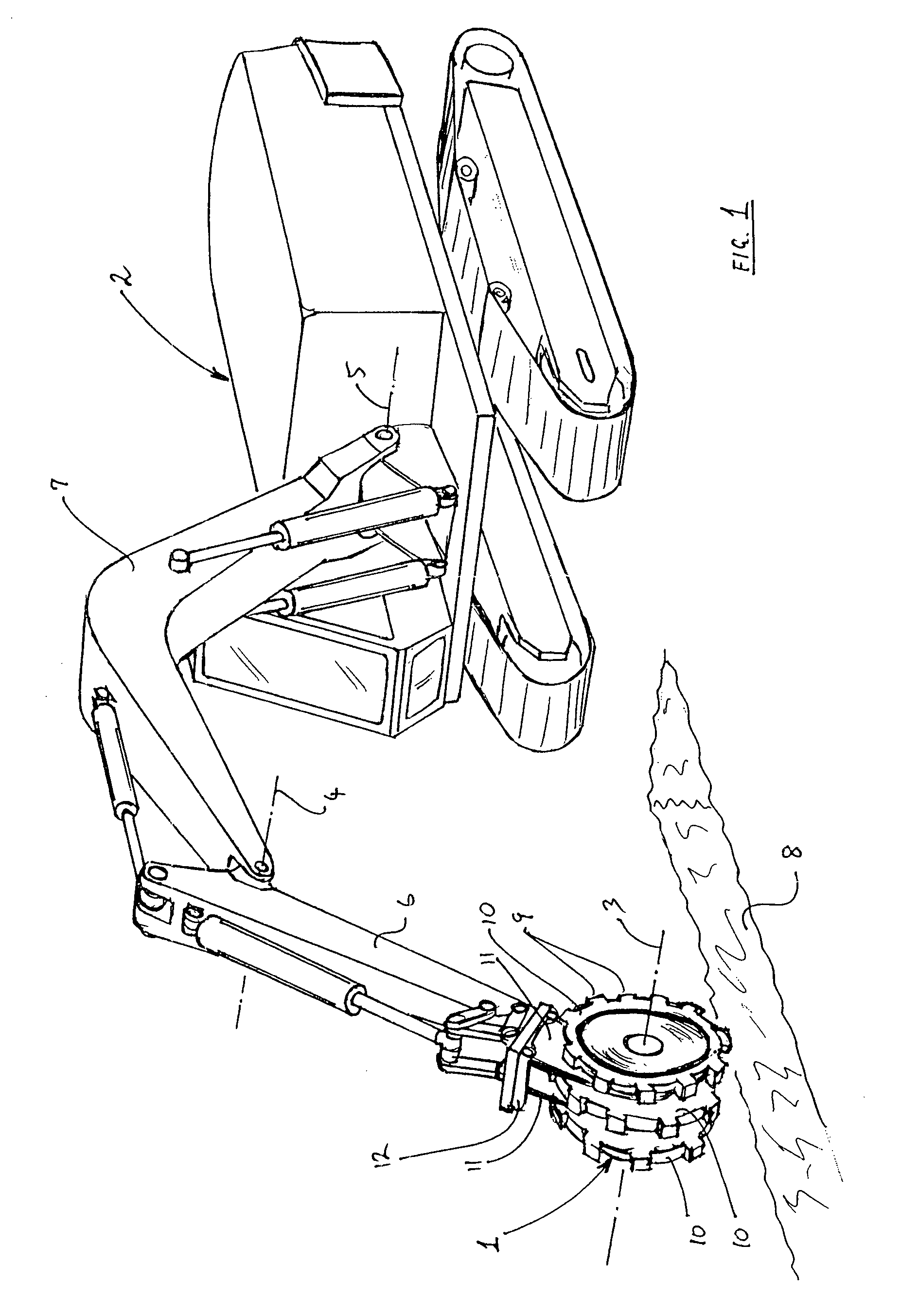
[0080]FIG. 1 shows a wheel-type compacting device 1 mounted on a backhoe excavator 2 and has been discussed above. The present invention provides an improved compacting device usable in the same way as compacting device 1.

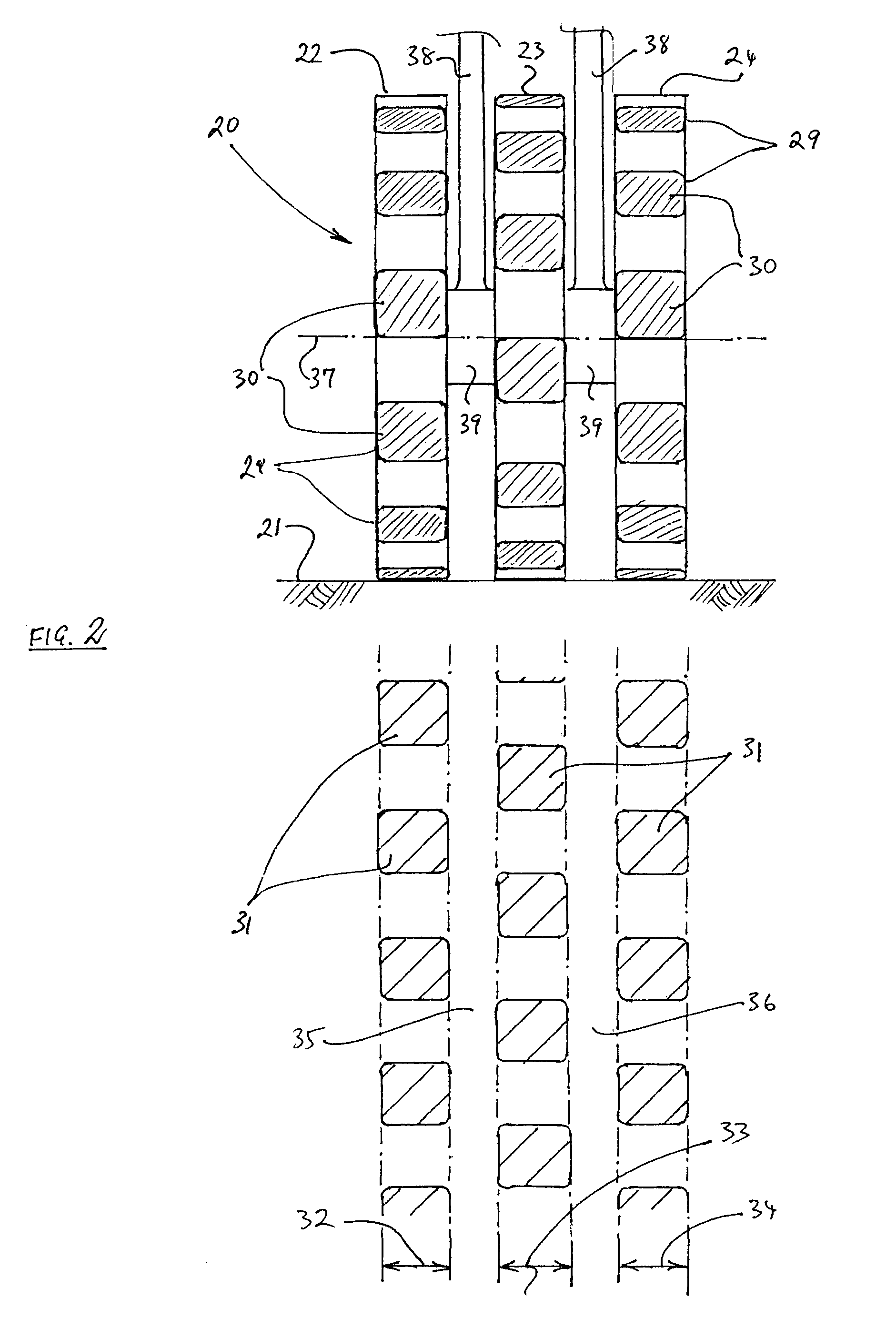
[0081]FIG. 2 shows a compacting device 20 such as that shown in the prior art device of FIG. 1. In the upper part of FIG. 2, a rear elevation of a compacting device 20 is shown, rolling on a substrate 21. Device 20 comprises three wheels 22, 23 and 24, that are mounted on a single shaft (not shown) so as to rotate together rather than independently. The shaft is in turn supported for rotation in bearing assemblies 39 mounted to a pair of support members 38 located between wheels 22 and 23, and 23 and 24 respectively. Wheel assemblies 22, 23 and 24 each have compacting feet 29 whose outer surfaces 30 (all shown shaded) contact substrate 21 as the device 20 is rolled over the substrate 21. No other constructional details of wheel assemblies 22, 23 and 24 are shown. T...


PUM

PropertyMeasurementUnit
offset angleaaaaaaaaaa

Abstract

A compacting device (40) for attachment to an earthmoving machine (2) to compact a substrate is described. The compacting device (40) includes a plurality of wheel assemblies (41, 42, 43) mounted for rotation in bearings (46). A support is also provided, having a base part (48) that is adapted to be mounted to the earthmoving machine (2). One or more bearing support members (47) extend from the base part (48) and between the wheel assemblies (41, 42, 43) to support the bearings (46). Each wheel assembly (41, 42, 43) includes a set of ground-contacting feet (44) secured to and peripherally spaced apart around a rim portion of the wheel assembly (41, 42, 43). In this arrangement, when the device (40) is rolled over the substrate a first foot of said set of ground engaging feet (44) contacts the substrate between axial width limits that differ from axial width limits of a second foot of said set of ground engaging feet (44).

Description

CROSS-REFERENCE TO RELATED APPLICATIONS[0001]The present application claims priority from Australian Provisional Patent Application No 2006902915 filed on 31 May 2006, the contents of which is incorporated herein by reference.FIELD OF THE INVENTION[0002]This invention relates to a compacting wheel apparatus of the type fitted to earthmoving machinery for compacting soil, particularly in trenches.BACKGROUND[0003]It is a requirement in cable- and pipe laying, and civil engineering in general, to compact soil in a trench, or other confined space, to return the soil to its original grade. For reasons of cost, safety and consistency of results, it is normal to fit a rotatable wheel or drum to a suitable earthmoving machine, the wheel or drum being rolled back and forth over the soil area to be compacted until a suitable level of compaction is obtained.[0004]FIG. 1 shows one such arrangement. A wheel-type compacting device 1 is mounted to a backhoe excavator 2 in place of the usual bucket...

Claims


Application Information

Patent Timeline
Patent Type & Authority Patents(United States)
IPC IPC(8): E01C19/26
CPCE02D3/026
Inventor JUZVA, ANDREWDAWSON, FRANCIS J
Owner ARMAGH (VIC) PTY LTD
Why Eureka
Try Eureka