Symmetric ultra-wideband omni-directional antenna

An omnidirectional antenna and ultra-wideband technology, which is applied in the direction of the antenna grounding switch structure connection, the structural form of the radiation element, etc., can solve the problems of unstable main radiation direction of the E plane, insufficient broadband index of the ultra-wideband omnidirectional antenna, etc., and achieve improved radiation Unstable pattern, good anti-vibration performance, uniform force effect

Active Publication Date: 2014-08-20
HARBIN INST OF TECH
View PDF1 Cites 0 Cited by
  • Summary
  • Abstract
  • Description
  • Claims
  • Application Information

AI Technical Summary

Problems solved by technology

[0004] The purpose of the present invention is to solve the problem that the broadband index of the existing ultra-wideband omnidirectional antenna is not enough, and the main radiation direction of the E plane is unstable, and then provide a symmetrical ultra-wideband omnidirectional antenna

Method used


Image

  • Symmetric ultra-wideband omni-directional antenna
  • Symmetric ultra-wideband omni-directional antenna
  • Symmetric ultra-wideband omni-directional antenna

Examples


specific Embodiment approach 1

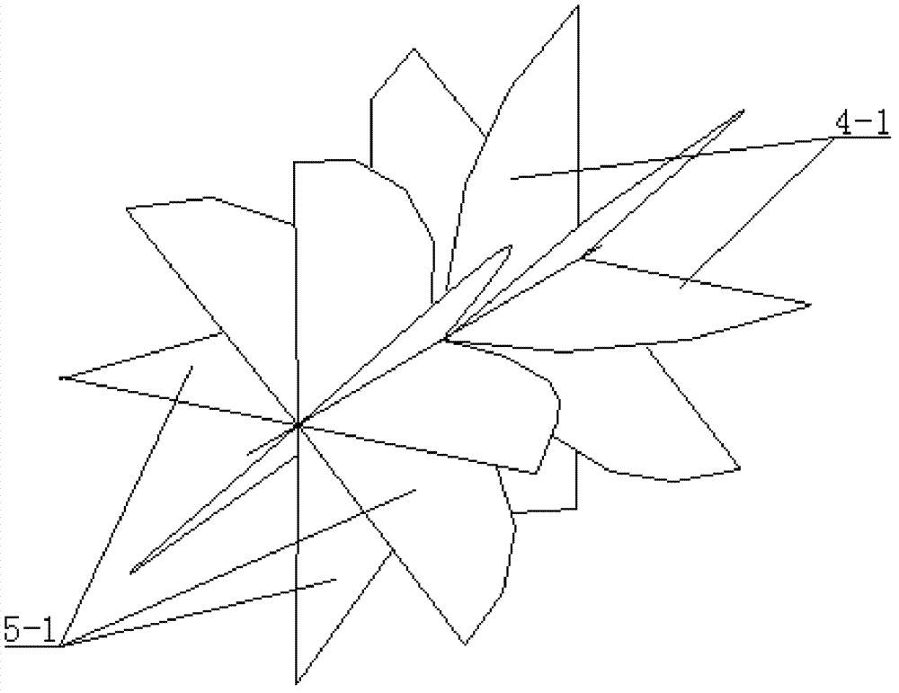
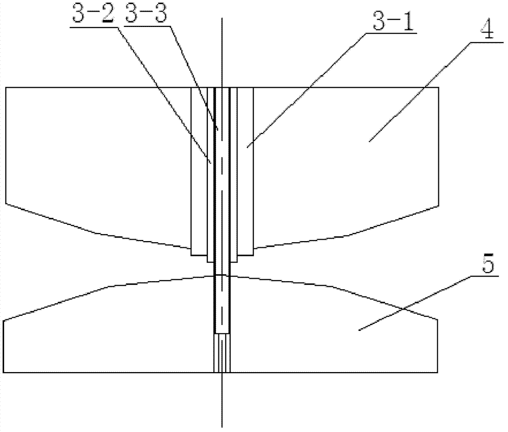
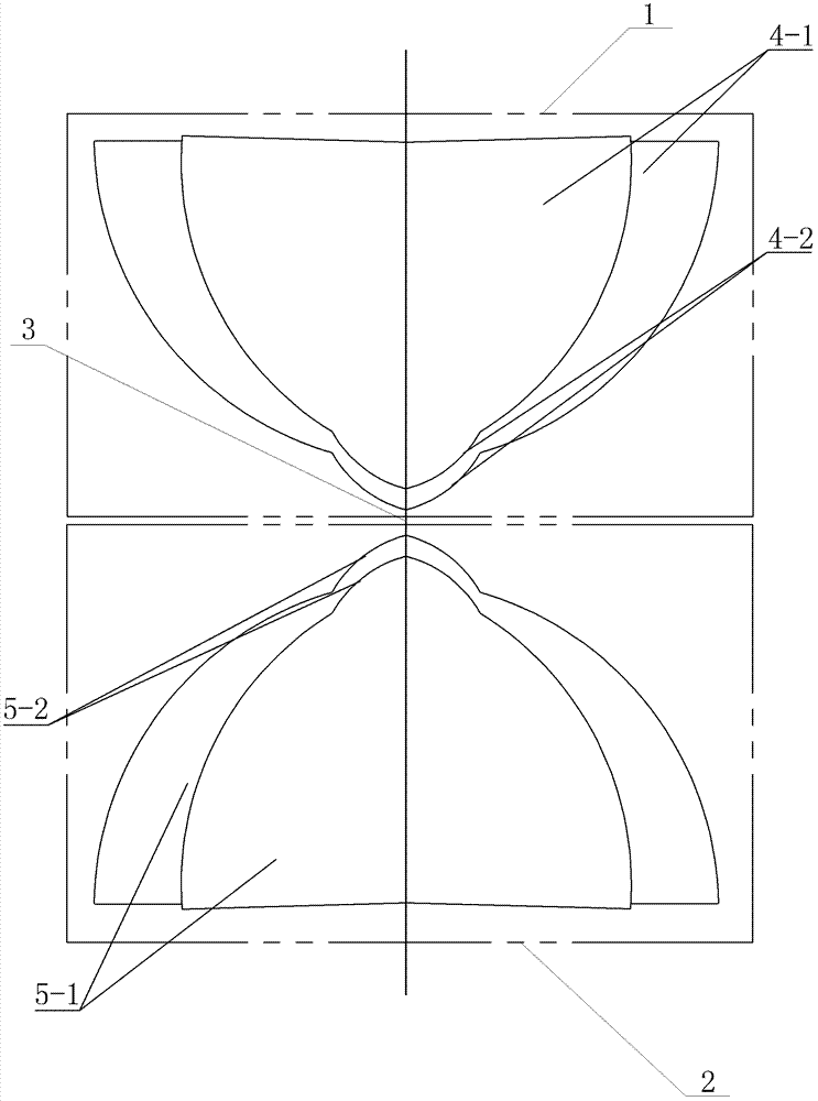
[0008] Specific implementation mode 1: Combination Figure 1-Figure 5 To describe this embodiment, a symmetrical ultra-wideband omnidirectional antenna of this embodiment includes a first radiating unit 1, a second radiating unit 2 and a feed coaxial line 3. The first radiating unit 1 includes a plurality of first metal plates 4 , Each first metal disc 4 includes a first quarter disc 4-1 and a first arc 4-2, the radius of the first arc 4-2 is smaller than the first quarter disc 4 The radius of 1, the first quarter disc 4-1 and the first arc 4-2 are connected up and down into one body and are located in the same plane. The first quarter disc 4-1 is at a distance from the end of the arc The position at a distance from the end is connected to the first end of the first arc 4-2 on the same side, and the vertical diameter of the first quarter disc 4-1 is the same as that of the first arc 4-2. The diameters are on the same axis, and the plurality of first metal disks 4 are evenly ar...

specific Embodiment approach 2

[0010] Specific implementation manner two: combination figure 1 with image 3 To illustrate this embodiment, the number of the first metal disk 4 and the number of the second metal disk 5 in this embodiment are both 6 or 8. With this configuration, the increase in the number of metal disks can improve the out-of-roundness of the antenna H-plane pattern, but too many metal disks will cause the antenna to be processed complex and the weight is too large. Therefore, the optimal number is 6 or 8. One. The other composition and connection relationship are the same as in the first embodiment.

specific Embodiment approach 3

[0011] Specific implementation mode three: combination figure 2 with image 3 To describe this embodiment, the feeding distance between the bottom of the first radiating unit 1 and the top of the second radiating unit 2 in this embodiment is 0.6 mm-1 mm. Such a setting can ensure that the antenna maintains a good impedance matching in the full working frequency band. The other composition and connection relationship are the same as in the first embodiment.


PUM


Abstract

The invention discloses a symmetric ultra-wideband omni-directional antenna which relates to ultra-wideband omni-directional antennas and solves the problems of the existing ultra-wideband omni-directional antenna in insufficient broadband index and unstable E plane main radiation direction. According to the symmetric ultra-wideband omni-directional antenna, a first quarter of wafer is vertically connected with a first circular arc as a whole and is located in the same plane with the first circular arc; the tail end of the circular arc of the first quarter of wafer is connected with the head end of the first circular arc located at the same side; a plurality of first metal discs are uniformly arranged by taking the vertical side as the center; a second quarter of wafer is vertically connected with a second circular arc as a whole and is located in the same plane with the second circular arc; the tail end of the circular arc of the second quarter of wafer is connected with the head end of the second circular arc located at the same side; a plurality of second metal discs are uniformly arranged by taking the vertical side as the center; the plurality of first metal discs of a first radiating unit pass through a hollow tube and are fixedly arranged on a coaxial line shielding layer; and the plurality of second metal discs of a second radiating unit which is arranged to be symmetric with the first radiating unit are fixedly arranged on a core line. The symmetric ultra-wideband omni-directional antenna is suitable for the fields, such as, electronic countermeasure, spread spectrum communication, and the like.

Description

Technical field [0001] The invention relates to an ultra-wideband omnidirectional antenna, in particular to a symmetrical ultra-wideband omnidirectional antenna. Background technique [0002] Ultra-wideband omnidirectional antennas are currently in mainstream applications such as monopole antennas, which use stand-alone radiating elements and floor structures. This type of antenna has a wide working frequency band, but the omnidirectionality of the H-plane pattern is very poor. The application date is On December 24, 2010, the application number was 201010604292.1, and the invention and creation of the patent named "omnidirectional radiation ultra-wideband antenna" solved the problem of poor omnidirectionality of the H-plane pattern. [0003] Existing ultra-wideband omnidirectional antennas such as meandering arm antennas, wire cone antennas and butterfly wire antennas have broadband characteristics, but the broadband indicators are not enough, and the main radiation direction of t...

Claims


Application Information

Patent Timeline
Patent Type & Authority Patents(China)
IPC IPC(8): H01Q1/36H01Q1/50
Inventor 张炀邱景辉张鹏宇特尼格尔郭文彬
Owner HARBIN INST OF TECH
Why Eureka
Try Eureka