Rotating cleaning brush

a cleaning brush and rotating technology, applied in vehicle cleaning, vehicle maintenance, transportation and packaging, etc., can solve the problems of limited working width of such a cleaning brush and inconvenient cleaning of structured surfaces, and achieve the effect of enlargement of the working area

Active Publication Date: 2019-01-08
DURCHLAUB THOMAS DR
View PDF19 Cites 0 Cited by
  • Summary
  • Abstract
  • Description
  • Claims
  • Application Information

AI Technical Summary

Benefits of technology

[0008]The bristles of the new cleaning brush are bent towards the longitudinal axis of the bristle carrier such that they overlap the bristles of the adjacent bristle bundles in a direction towards the second end of the cleaning brush. In this way, the new rotating cleaning brush is able to adapt its working region of the surface to be cleaned without having to stop the cleaning process.
[0009]The bristles of all or at least many bristle bundles may have the same length. In this case, due to the rounded design of the second end of the bristle carrier, they form a rounded tip. Due to this shape, it is possible to clean finely and deeply structured surfaces. The bristles being located closer to the second end are moved towards the first end when the pressure is increased, and the bristles being located closer to the first end get in contact with the surface to be cleaned. The working width of the cleaning brush is automatically increased. At the same time, the bristles being located closer to the first end counteract a further movement of the bristles being located closer to the second end in a stabilizing way. In this way, uncontrolled lateral movement of the cleaning brush is prevented.
[0010]Furthermore, the working region can be adapted by changing the rotational velocity of the driving shaft of the machine rotatingly driving the cleaning brush about the longitudinal axis. This is because of the centrifugal force resulting in the bristles bending in a radial direction of the bristle carrier when the number of rotations of the driving machine is increased. In this way, the working region is increased.
[0013]For cleaning larger surfaces having a rather flat structure, it may be preferred that the free ends of the bristles end in one common surface. In this way, all bristles get in direct contact with the surface to be cleaned. When the pressure is increased, the bristles move towards the outside resulting in an enlargement of the working region.
[0014]The openings may be arranged in the shell surface of the bristle carrier in a circular configuration. In this way, the bristles being located closer to the first end support the bristles being located closer to the second end in a reliable and uniform way.
[0016]The bristles may include at least two plastic fibers. The bristles may have free ends, and the plastic fibers may be designed such that they are spliced at the free ends. In this way, the cleaning brush is comparatively soft and suitable for cleaning sensitive surfaces without causing damage. The free ends are finer, and they can adapt to the surface to be cleaned in an improved way.

Problems solved by technology

However, the working width of such a cleaning brush is limited.
However, such cleaning brushes are not suitable for cleaning structured surfaces.

Method used


Image

  • Rotating cleaning brush
  • Rotating cleaning brush
  • Rotating cleaning brush

Examples


Embodiment Construction

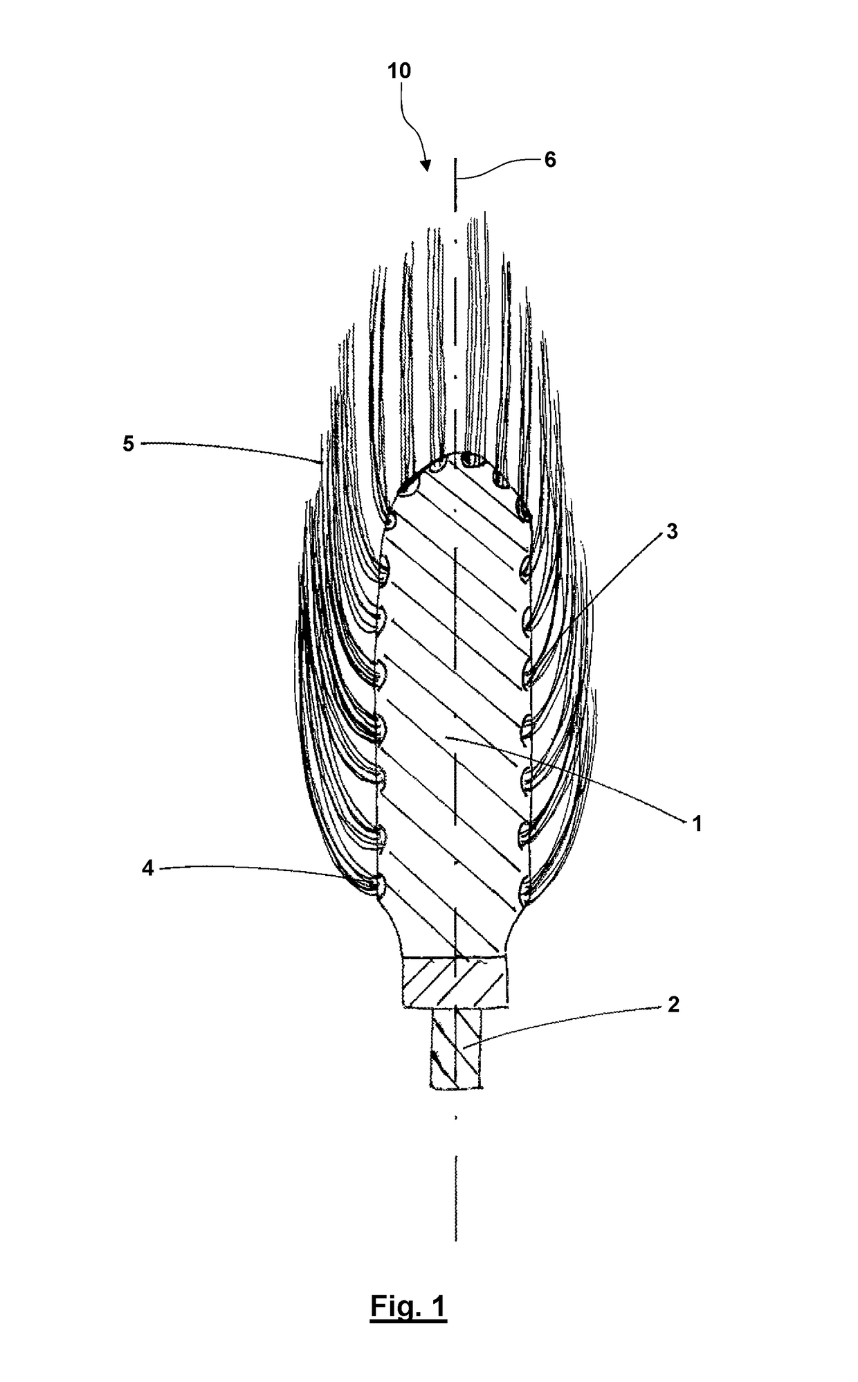
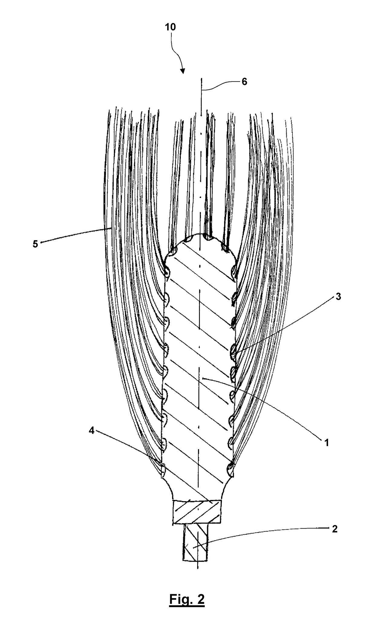
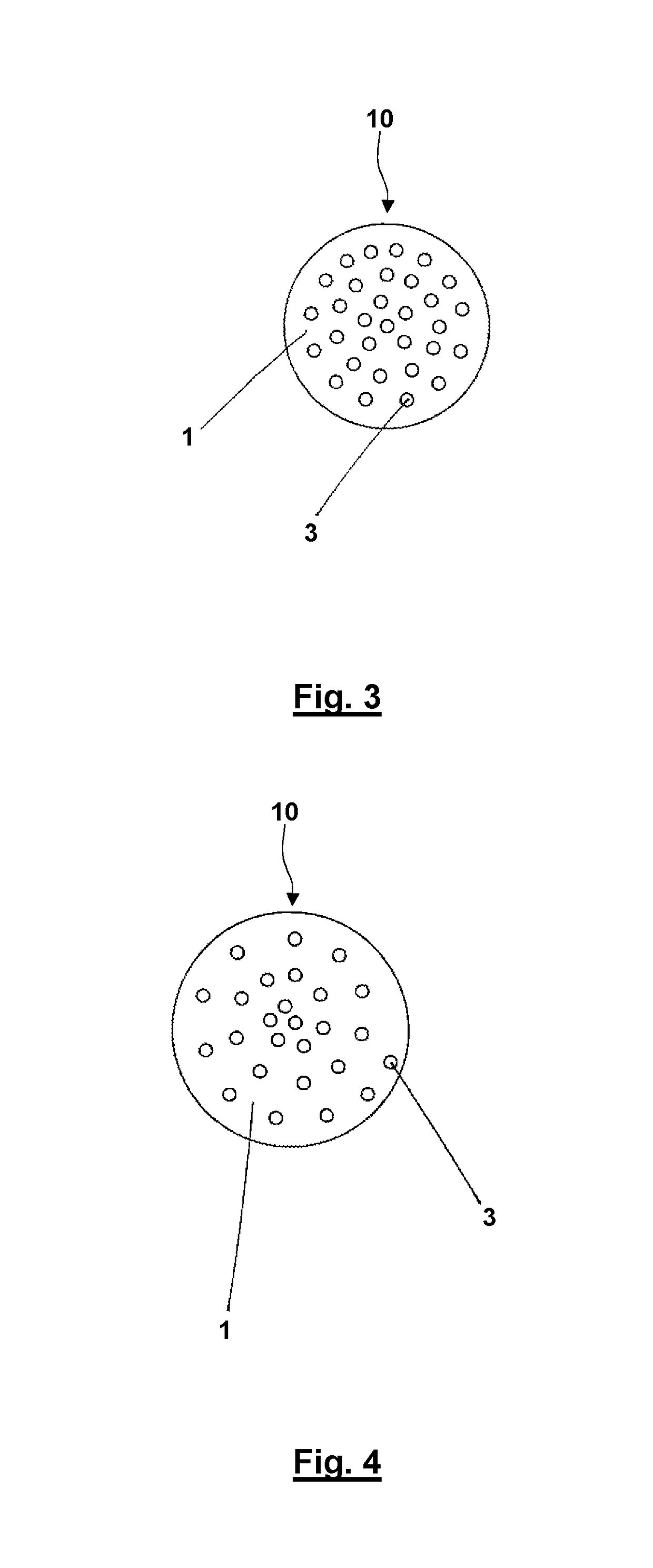
[0024]A new cleaning brush 10 including a cylindrical bristle carrier 1 having a rounded second end is illustrated in the drawings. The bristle carrier 1 could also have the shape of a rounded cone. A connection pin 2 is fixedly located in the region of the first end of the bristle carrier 1 as seen in the direction of the longitudinal axis 6 of the bristle carrier 1. The connection pin 2 is destined to be clamped in the chuck of a machine including a rotating drive shaft, for example a portable drill. Openings 3 are arranged in the shell surface of the bristle carrier 1.

[0025]As it is to be seen in FIG. 1, bristle bundles 4 are fixedly located in the opening 3. Each of the bristle bundles 4 includes a plurality of bristle 5. The bristles 5 are bent towards the longitudinal axis 6 of the bristle carrier 1 and the run parallel to the longitudinal axis 6. In this exemplary embodiment, all bristles 5 have the same length. The bristles 5 being located closer to the lower first end of th...


PUM


Abstract

A rotating cleaning brush includes a connection pin to be clamped in a chuck of a machine for rotatingly driving the cleaning brush about its longitudinal axis. The cleaning brush includes a bristle carrier including a plurality of openings. The bristle carrier includes a first bristle bundle and a second bristle bundle being adjacent along the longitudinal axis. The first bristle bundle is located closer to the first end region of the cleaning brush than the second bristle bundle. Each of the bristle bundles includes a plurality of bristles and is located in one of the openings. The bristles of the first bristle bundle are designed to bend towards the longitudinal axis and then run parallel to the longitudinal axis so as to overlap the opening in which the second bristle bundle is arranged.

Description

CROSS REFERENCE TO RELATED APPLICATIONS[0001]This application claims priority to co-pending German utility model No. DE 20 2015 104 378.3 filed Aug. 19, 2015.FIELD OF THE INVENTION[0002]The present invention relates to a rotating cleaning brush including a connection pin to be clamped in the chuck of a machine for rotatingly driving the cleaning brush about the longitudinal axis.[0003]Such a rotating cleaning brush may be used for cleaning rims of automobiles, for example.BACKGROUND OF THE INVENTION[0004]A cleaning brush is known from German Utility Model No. DE 299 09 346 U1. The cleaning brush includes a conical bristle carrier and is destined to be clamped in a chuck of a machine including a rotating drive shaft. The cleaning brush is suitable for cleaning cavities and impressions, but it is not suitable for cleaning larger surfaces.[0005]Other rotating cleaning brushes are known from German Utility Model Nos. DE 20 2014 003 325 U1, DE 299 16 951 U1 and DE 20 2007 013 760 U1.SUMM...

Claims


Application Information

Patent Timeline
Patent Type & Authority Patents(United States)
IPC IPC(8): A46B9/02B60S3/04A46B13/02B08B1/00A46B13/00B60S3/06B08B1/04
CPCB08B1/002A46B9/02A46B13/001B60S3/066B08B1/04B60S3/042A46B13/02
Inventor KALFE, AHMET
Owner DURCHLAUB THOMAS DR
Why Eureka
Try Eureka