Transport belt for transporting fibre bundle for compacting

A conveyor belt and fiber technology, applied in textiles and papermaking, drafting equipment, spinning machines, etc., can solve problems such as pollution in the air-permeable work area, and achieve the effect of reducing wear

Inactive Publication Date: 2007-01-10
MASCHINENFABRIK RIETER AG
View PDF3 Cites 0 Cited by
  • Summary
  • Abstract
  • Description
  • Claims
  • Application Information

AI Technical Summary

Problems solved by technology

However, the part of the gas-permeable work area that is no longer suctioned is contaminated

Method used


Image

  • Transport belt for transporting fibre bundle for compacting
  • Transport belt for transporting fibre bundle for compacting
  • Transport belt for transporting fibre bundle for compacting

Examples


Embodiment Construction

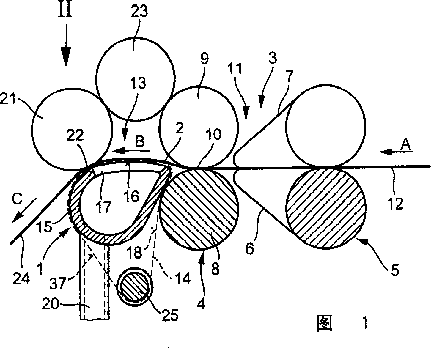
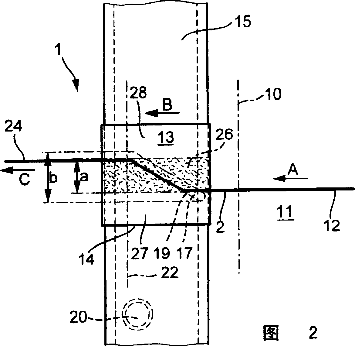
[0015] In FIGS. 1 and 2 only the area of ​​the device 1 for compacting the drawn fiber strand 2 of a spinning machine, in particular a ring spinning machine, is shown. The device 1 shows a pair of output rollers 4 directly connected to a drafting device 3 and a pair of apron rollers 5 arranged upstream in the conveying direction A. The apron roller 5 guides a lower apron 6 and an upper apron 7 . The delivery roller pair 4 includes a driven delivery groove roller 8 and a delivery pressure roller 9 elastically pressed against the delivery groove roller. The delivery roller pair 4 thus delimits a delivery nip line 10 which forms the end of the drafting zone 11 of the drafting device 3 .

[0016] In the drafting device 3, a fiber sliver or roving 12 is drawn in the conveying direction A to the desired fineness in a known manner. This drafting effect ends at the output nip line 10, so the fiber strands 2 that have been drafted but not yet twisted are laid flat forward from this p...


PUM


Abstract

A transport belt for transporting a fibre bundle for compacting over an inclined suction slot (17) on a spinning machine compacting zone, terminating with a pinch-point is disclosed. Said transport belt comprises a support surface (18), by means of which said belt runs on a stationary slide surface (16) comprising the suction slot (17). The transport belt further comprises an air-permeable working section (26) facing the suction slot (17) and boundary regions (27, 28), laterally adjacent to the air-permeable working section (26), which are not air-permeable. The air-permeable working region (26) has a working width which is narrower than the width which is actively sucked by the suction slot (17).

Description

technical field [0001] The invention relates to a conveyor belt for conveying a sliver to be compacted through an inclined suction gap in a compaction zone of a spinning machine ending in a nip, which has a The bearing surface slides on the sliding surface of the suction gap; has a gas-permeable working area in addition to the suction gap; and has gas-permeable edge regions on both sides next to the gas-permeable working area. Background technique [0002] On conveyor belts of this type (DE 198 37 179 A1), the ends of the sloping suction slots are located inside the air-permeable working area, so that suction is no longer received at its edge, ie in the area of ​​the transition to the air-permeable edge area. The suction effect of the gap. It has been shown that no fiber fluff occurs in the working area as long as it is subjected to the suction effect of the suction gap. Despite the high amount of dust, the conveyor belt remains clean in the suction area of ​​the suction g...

Claims


Application Information

Patent Timeline
IPC IPC(8): D01H5/86D01H5/72D01H5/64D01H5/26D01H5/66
CPCD01H5/72D01H5/86
Inventor F·施塔勒克
Owner MASCHINENFABRIK RIETER AG
Why Eureka
Try Eureka