Observation wheel type ride

a technology of observation wheel and ride, which is applied in the direction of great wheels, russian swings, amusements, etc., to achieve the effect of simple structural connection between cable and wheel and/or transportation means

Active Publication Date: 2012-07-10
RONALD BUSSINK AMUSEMENT DESIGN
View PDF6 Cites 11 Cited by
  • Summary
  • Abstract
  • Description
  • Claims
  • Application Information

AI Technical Summary

Benefits of technology

[0013]Due to the deflection of the cable in the sideways or lateral direction, a collision of the passenger cabins can be avoided even if the cabins project over the lateral end of the wheel and the loop of the drive cable, which is affixed to the wheel. This allows a design of the passenger cabins, which is not limited by the lateral dimensions of the wheel. Further, as the drive cable is deflected sideways before entering the rotary drive, the observation wheel like amusement ride according to the invention allows for a location of the rotary drive adjacent to the wheel. Thus, a positioning of the rotary drive directly underneath the wheel is not necessary. In comparison with classical drive systems made of several synchronized drives, the observation wheel according to the invention may be used with a single drive and thus does not require a synchronizing of several drives, which is known as a problem.
[0020]According to another advantageous feature of the present invention, the rotary drive has a drive pulley for guiding the drive cable, with the deflection means including two additional guide pulleys arranged between the deflection pulley and the drive pulley. The two guide pulleys may be provided to deflect the drive cable again, which allows for a positioning of the drive pulley parallel or almost parallel to the wheel.
[0024]According to another advantageous feature of the present invention, the cable may frictionally engage in a plurality of cable shoes, which can be distributed, preferably evenly, along the circumference of the wheel and / or the transportation means. This allows for a simple structural connection of the cable and the wheel and / or the transportation means.

Problems solved by technology

The cable drive system according to European Patent Document EP 1 790 402 A1 is disadvantageous in that it requires that the drive mechanism is located directly underneath the annular structure.

Method used


Image

  • Observation wheel type ride
  • Observation wheel type ride
  • Observation wheel type ride

Examples


Embodiment Construction

[0034]Throughout all the figures, same or corresponding elements may generally be indicated by same reference numerals. These depicted embodiments are to be understood as illustrative of the invention and not as limiting in any way. It should also be understood that the figures are not necessarily to scale and that the embodiments are sometimes illustrated by graphic symbols, phantom lines, diagrammatic representations and fragmentary views. In certain instances, details which are not necessary for an understanding of the present invention or which render other details difficult to perceive may have been omitted.

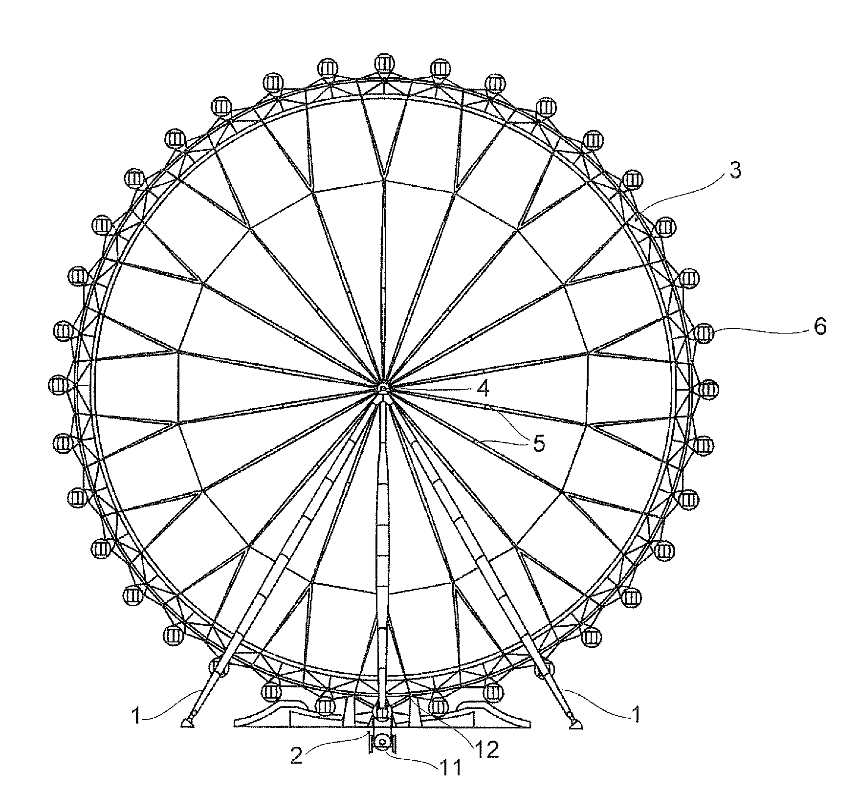
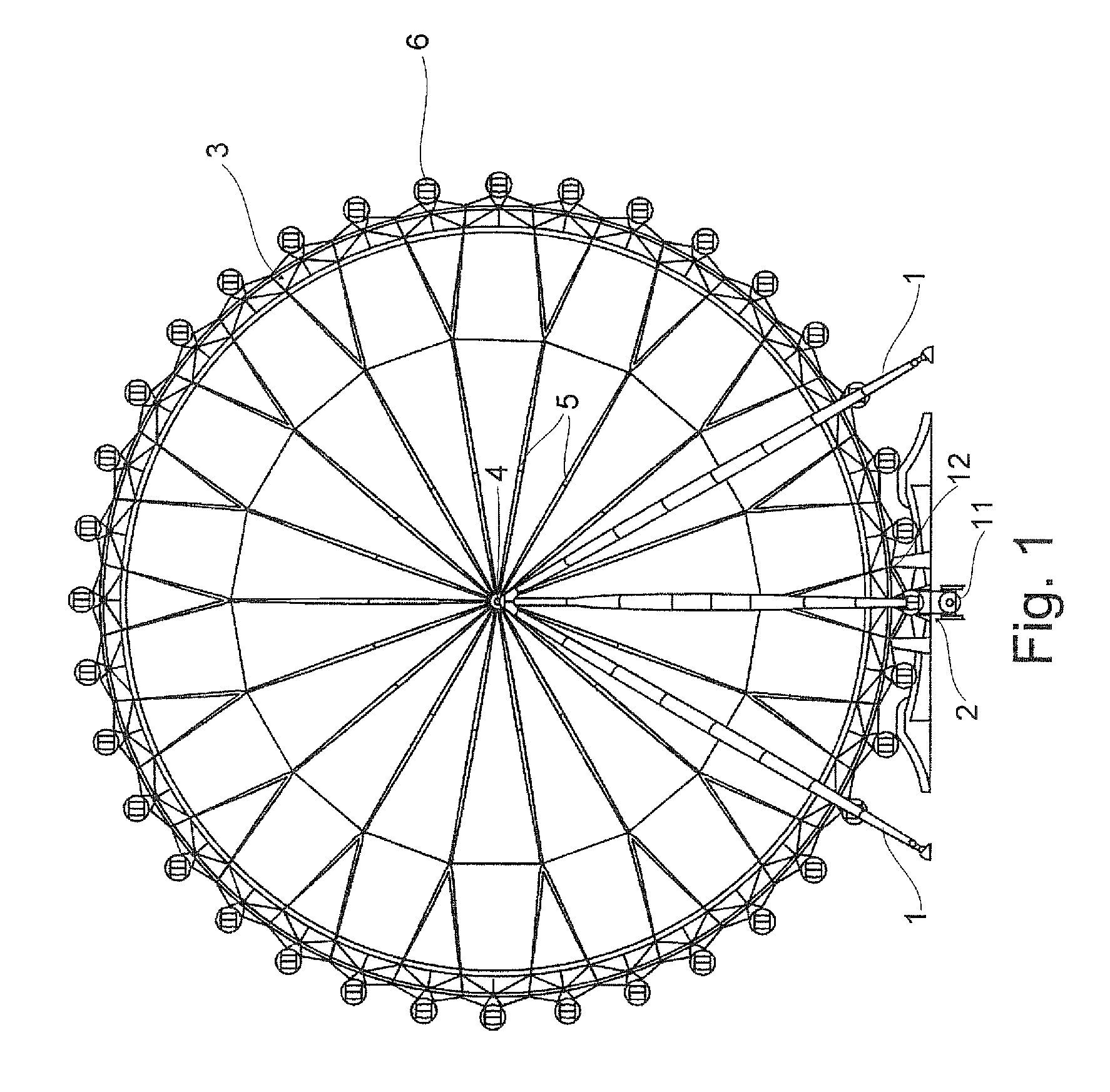
[0035]Turning now to the drawing, and in particular to FIG. 1, there is shown a rear view of a first embodiment of an observation wheel according to the present invention. The observation wheel shown is a stationary observation wheel, i.e. it is designed to be situated in the same location for the whole operation time. It is self-evident, that also movable observation wheel ...


PUM


Abstract

An observation wheel type ride includes a support structure, a wheel which is rotatable mounted in the support structure and / or includes a transportation device movably supported on the wheel, and a drive mechanism. The drive mechanism includes a rotary drive and a drive cable, wherein a section of the drive cable is detachably fixed to a circumference of the wheel and / or to the transportation device for transmitting the rotary movement of the rotary drive to the wheel and / or to the transportation device. A deflection assembly deflects in a lateral direction with respect to the wheel that section of the drive cable, which is led over the rotary drive.

Description

CROSS-REFERENCES TO RELATED APPLICATIONS[0001]This application claims the benefit of prior filed U.S. Provisional Application No. 61 / 175,606, filed May 5, 2009, pursuant to 35 U.S.C. 119(e).[0002]This application claims the priority of European Patent Application, Serial No. 09 006 123.5, filed May 5, 2009, pursuant to 35 U.S.C. 119(a)-(d).[0003]The contents of U.S. Provisional Application No. 61 / 175,606 and European Patent Application, Serial No. 09 006 123.5 are incorporated herein by reference in their entirety as if fully set forth herein.BACKGROUND OF THE INVENTION[0004]The present invention relates to an observation wheel type ride.[0005]The following discussion of related art is provided to assist the reader in understanding the advantages of the invention, and is not to be construed as an admission that this related art is prior art to this invention.[0006]Observation wheels or giant wheels are common in cities and on fairgrounds. Due to their height and their slow movement ...

Claims


Application Information

Patent Timeline
Patent Type & Authority Patents(United States)
IPC IPC(8): A63G27/08A63G27/00
CPCA63G27/00
Inventor BUSSINK, RONALD ALEXANDERLINS, STEPHANFRAUNDORFER, JOHANNES
Owner RONALD BUSSINK AMUSEMENT DESIGN
Why Eureka
Try Eureka