
Apparatus and method for applying sustained tension on a tether

a technology of sustained tension and tether, which is applied in the field of spinal deformation correction, to achieve the effect of accurate, permanent measurable and adjustable tension level

Active Publication Date: 2012-07-10
WARSAW ORTHOPEDIC INC
View PDF3 Cites 24 Cited by
  • Summary
  • Abstract
  • Description
  • Claims
  • Application Information

AI Technical Summary

Benefits of technology

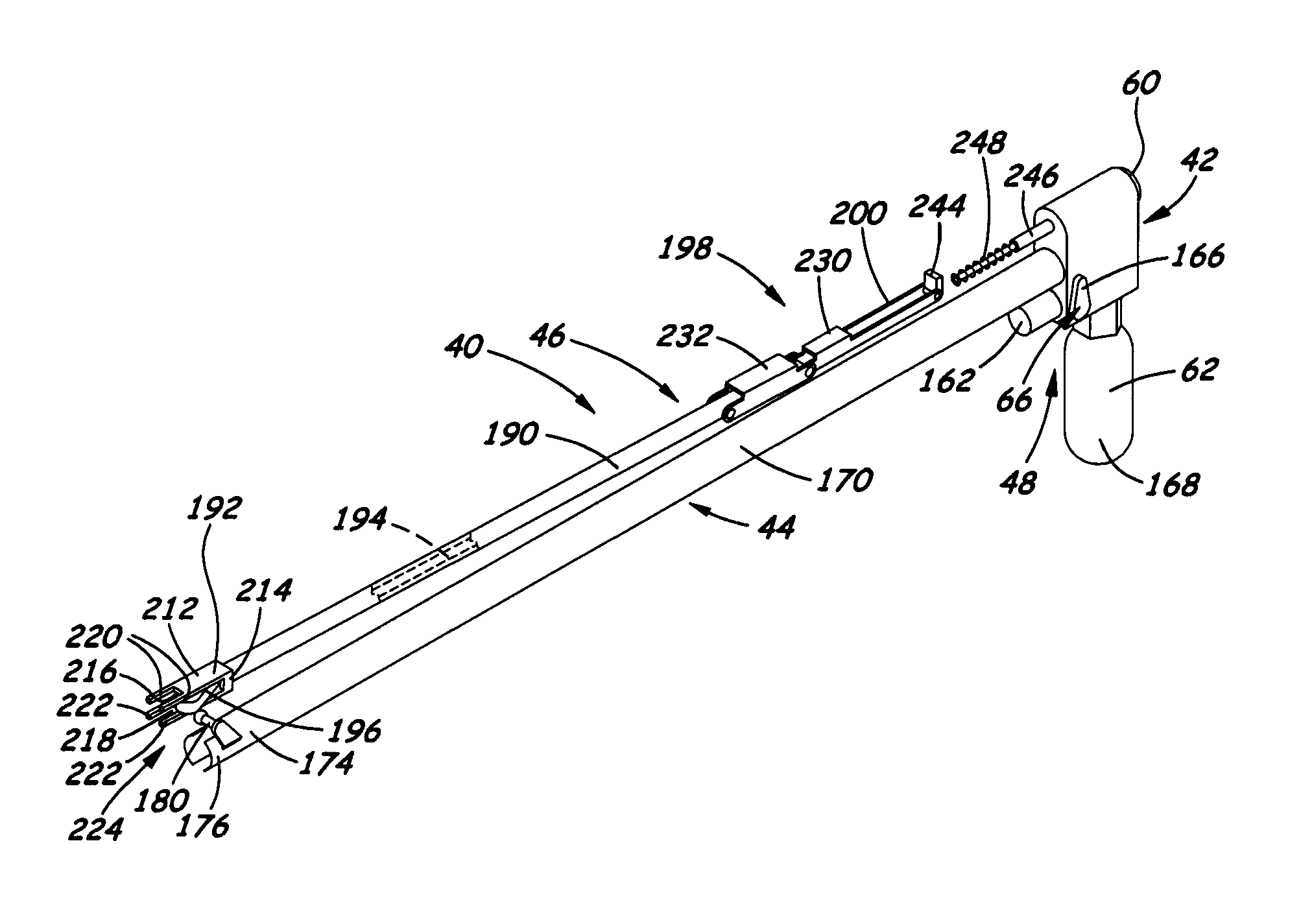
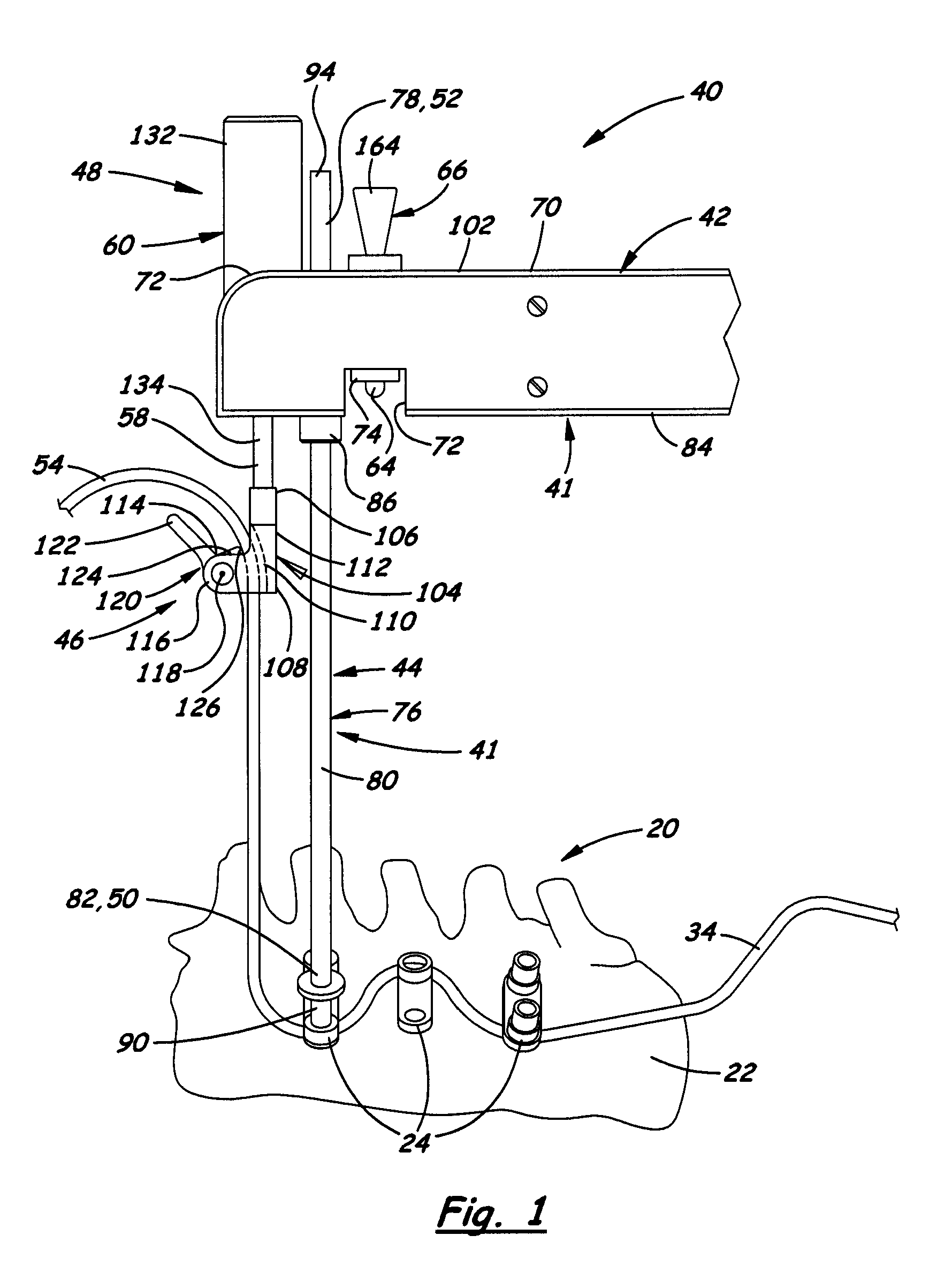
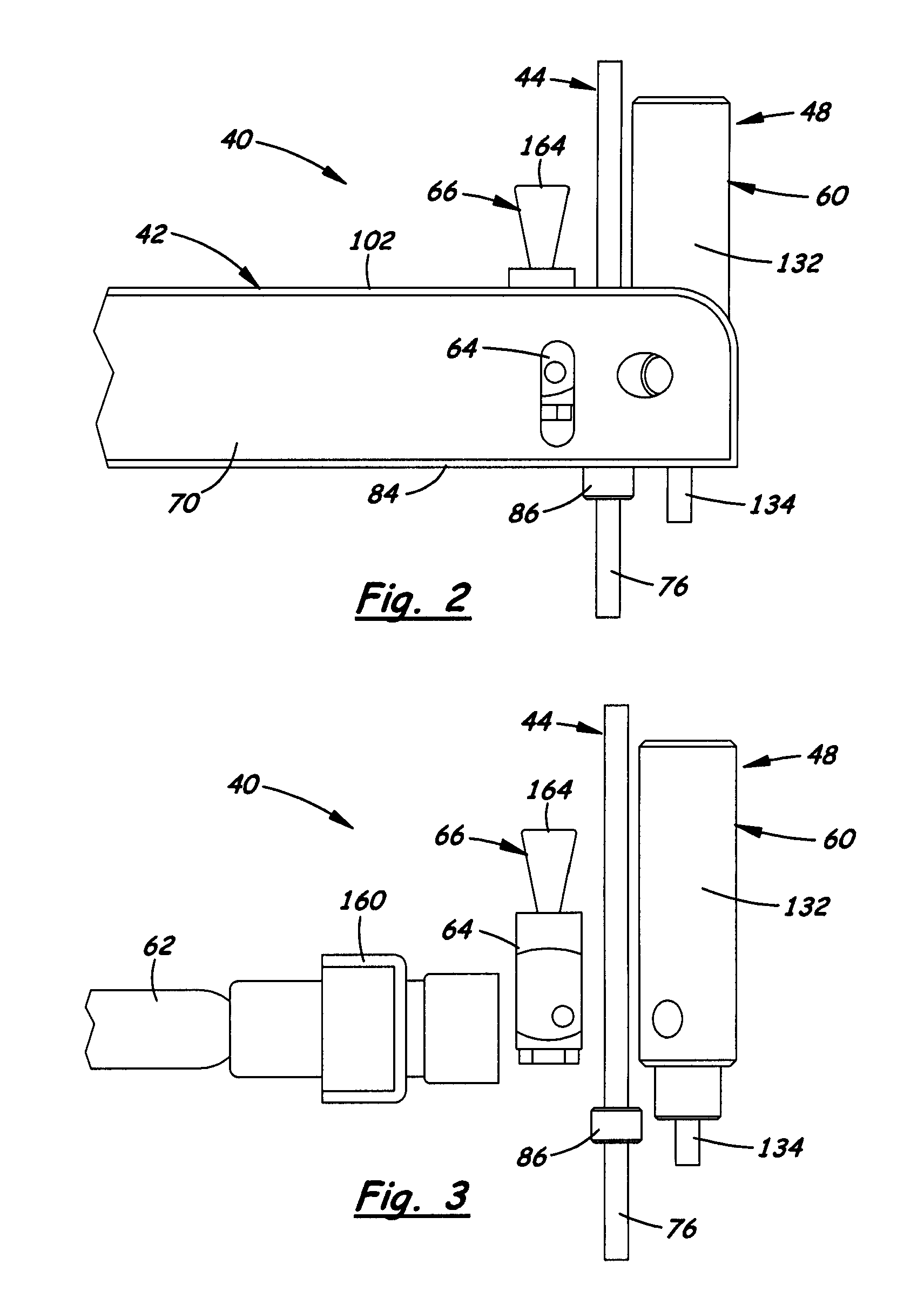
The present invention provides an apparatus and method for applying sustained tension on a tether in a treatment site. The apparatus includes a positioning mechanism, a gripping mechanism, and a pressurized fluid actuated mechanism. The pressurized fluid actuated mechanism is supported by the positioning mechanism and operable to apply a controlled tensioning force via the gripping mechanism to the tether independently from the tether displacement and thereby to place the tether under a desired level of sustained tension. The method includes positioning an actuating device at a fixed distance relative to a target in the treatment site, coupling a portion of the tether that extends from the treatment site with the actuating device, and applying a fluid under pressure from a pressurized fluid source to the actuating device sufficient to cause the actuating device to apply a desired tensioning force to the tether independently from the tether displacement and thereby to place the tether under a desired level of sustained tension. The technical effect of this invention is the ability to accurately, permanently measure and adjust the level of tension in a tether independently from the tether displacement.

Problems solved by technology

The fact that this undesirable event may occur from time to time demonstrates the need for a technique and means to carry out permanent tension measurement and adjustment before and during the time when the tether is fixed or constrained.

Method used


Image

  • Apparatus and method for applying sustained tension on a tether
  • Apparatus and method for applying sustained tension on a tether
  • Apparatus and method for applying sustained tension on a tether

Examples


Embodiment Construction

[0032]The present invention now will be described more fully hereinafter with reference to the accompanying drawings, in which some, but not all embodiments of the invention are shown. Indeed, the invention may be embodied in many different forms and should not be construed as limited to the embodiments set forth herein; rather, these embodiments are provided so that this disclosure will satisfy applicable legal requirements. Like numerals refer to like elements throughout the views. Particularly, in the following disclosure, the invention is described and illustrated in an application where the tether is tensioned and secured to an implant. However, the implant is merely one example of a type of target to which the invention can be applied. Another example is bone itself to which the tensioned tether can be secured. Therefore, it should be understood that, as reflected by the appended claims, the invention is not limited by the particular application disclosed and illustrated herei...


PUM


Abstract

Apparatus for applying sustained tension on tether in treatment site includes a positioning mechanism, gripping mechanism and pressurized fluid actuated mechanism. The positioning mechanism is operable to position the pressurized fluid actuated mechanism at a fixed distance relative to treatment site, and to engage a target at treatment site and secure the tether proximate to the target. The gripping mechanism is operable to selectively grip the tether and maintain tether when tether is held in tension. The pressurized fluid actuated mechanism is selectively operable to apply desired pulling force on gripping mechanism directed away from treatment site so as to transmit and apply in a sustained manner the desired pulling force on the tether independently from the tether displacement and place it under desired level of tension while the tether is being secured.

Description

BACKGROUND[0001]1. Field of the Invention[0002]The present invention relates generally to correction of spinal deformities and, more particularly, to an apparatus and a method for applying sustained tension on a tether used in a treatment site.[0003]2. Description of the Related Art[0004]Tools and methods have been developed for tensioning flexible elongate media (hereinafter generically referred to as a tether) used in various surgical applications. One such surgical application is correction of pediatric deformities. During such surgical procedure, it is required that the tether has a predetermined tension before fixing it in place. Tensioning tools, in particular, need to provide a way to impart some predetermined measurable tension on the tether and maintain this tension before the tether is fixed or constrained in some manner to a target, such as bone or an implanted anchor device, during a medical procedure in a treatment site.[0005]However, at various times after the desired ...

Claims


Application Information

Patent Timeline
Patent Type & Authority Patents(United States)
IPC IPC(8): A61B17/58
CPCA61B17/7022A61B17/7083A61B17/7091A61B17/8869A61B17/7032
Inventor GIL, CARLOS E.ZOLOTOV, ALEKSANDR G.MAY, JASON M.
Owner WARSAW ORTHOPEDIC INC
Learn More