
Edge detection based on background change

a background change and edge detection technology, applied in the field of computer vision, can solve the problems of manual activation of signals by wheelchair users, inability to manually activate signals for wheelchair users, and inability to achieve optimal results

Inactive Publication Date: 2006-04-18
MITSUBISHI ELECTRIC RES LAB INC
View PDF7 Cites 67 Cited by
  • Summary
  • Abstract
  • Description
  • Claims
  • Application Information

AI Technical Summary

Benefits of technology

[0017]In another application, the wheelchair user is waiting for an elevator, or some other type of lifting device. Upon detecting the wheelchair user in this case, specialized elevator services can be provided. For example, the elevator floor can be leveled more precisely with the floor, and the elevator door can be held open for a longer period of time on entry and exit of the wheelchair. In addition, an elevator car specially designed for transporting wheelchairs can be assigned to service the wheelchair user, or servicing can be prioritized.

Problems solved by technology

However, not all wheelchair users are able to manually active a signal.
There may be other reasons why a manually system is impractical, or less than optimal.

Method used


Image

  • Edge detection based on background change
  • Edge detection based on background change
  • Edge detection based on background change

Examples


Embodiment Construction

[0028]System Overview

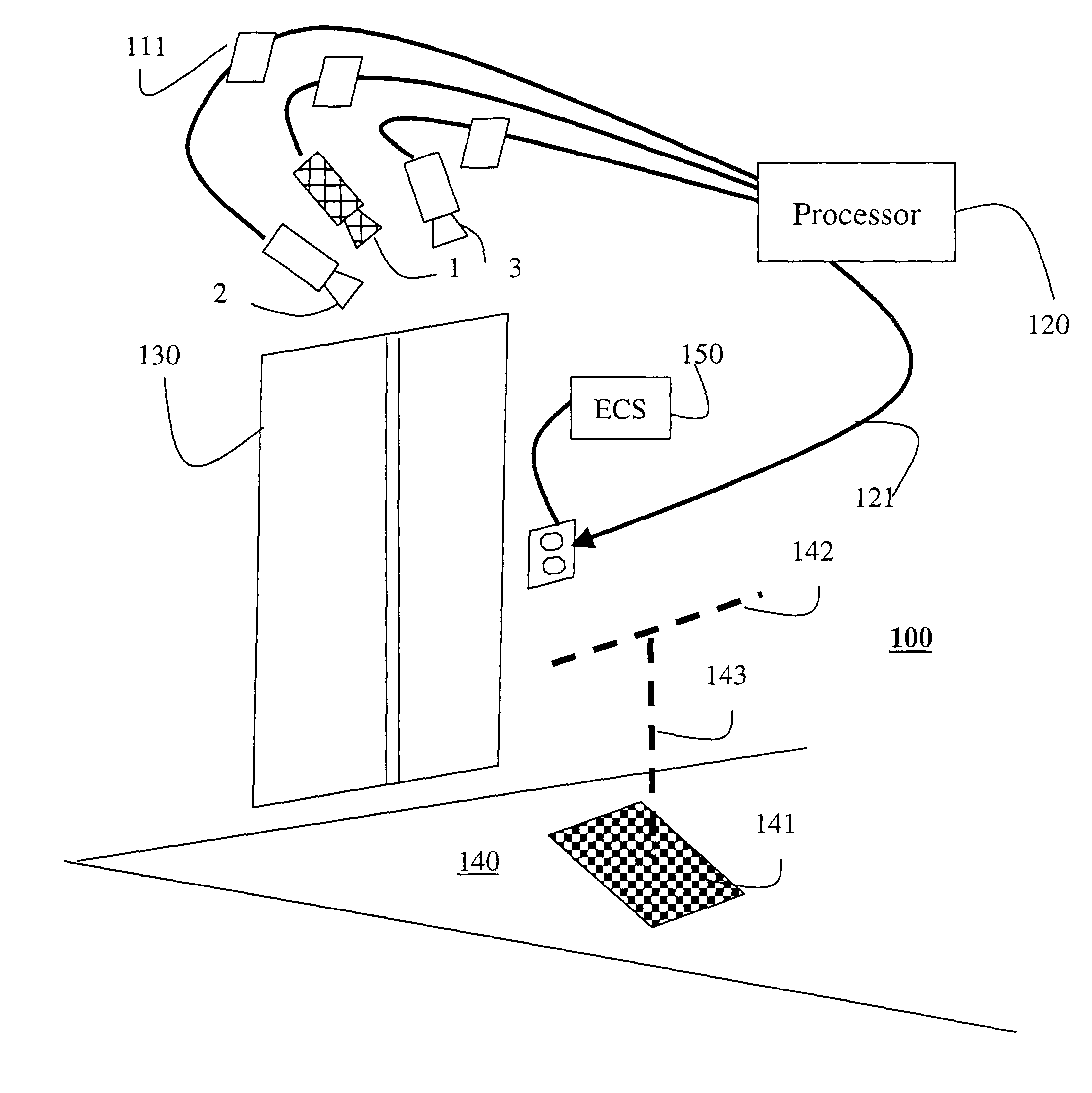
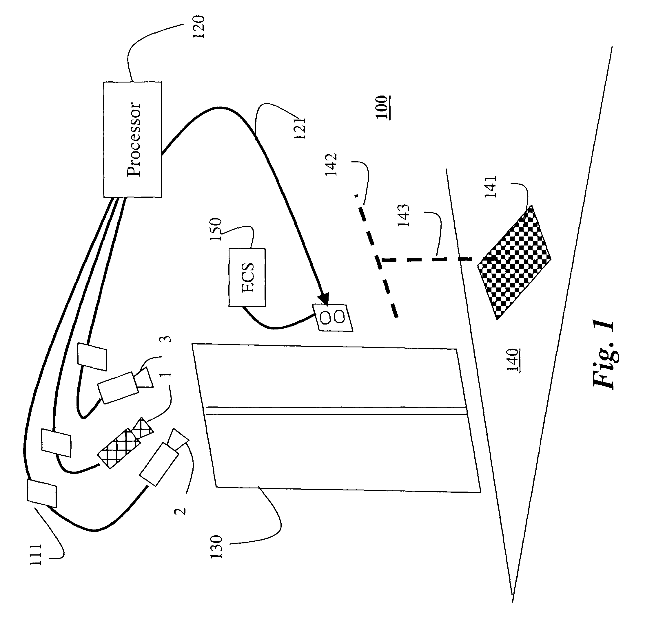
[0029]FIG. 1 shows an object detection 100 according to the invention. The system 100 includes multiple cameras 1, 2 and 3, e.g., three, having their outputs connected to a processor 120 configured to perform computer vision processing, as described herein. An output signal 121 of the processor 120 is connected to an external system, for example, an elevator control system (ECS) 150. The external system 150 is controlled according to what is observed by the cameras.

[0030]The cameras 1–3 are mounted above elevator doors 130 so that images 111 acquired by the cameras are of a scene 140 in front of the elevator doors. It should be noted that the cameras can be mounted anywhere proximate to the scene. The cameras can use gray-scale or color sensors. The intrinsic and extrinsic parameters of the cameras 1–3 can be determined using any known calibration procedure. For purpose described below, the center (cross-hatched) camera 1 is the primary camera, and the two other...


PUM


Abstract

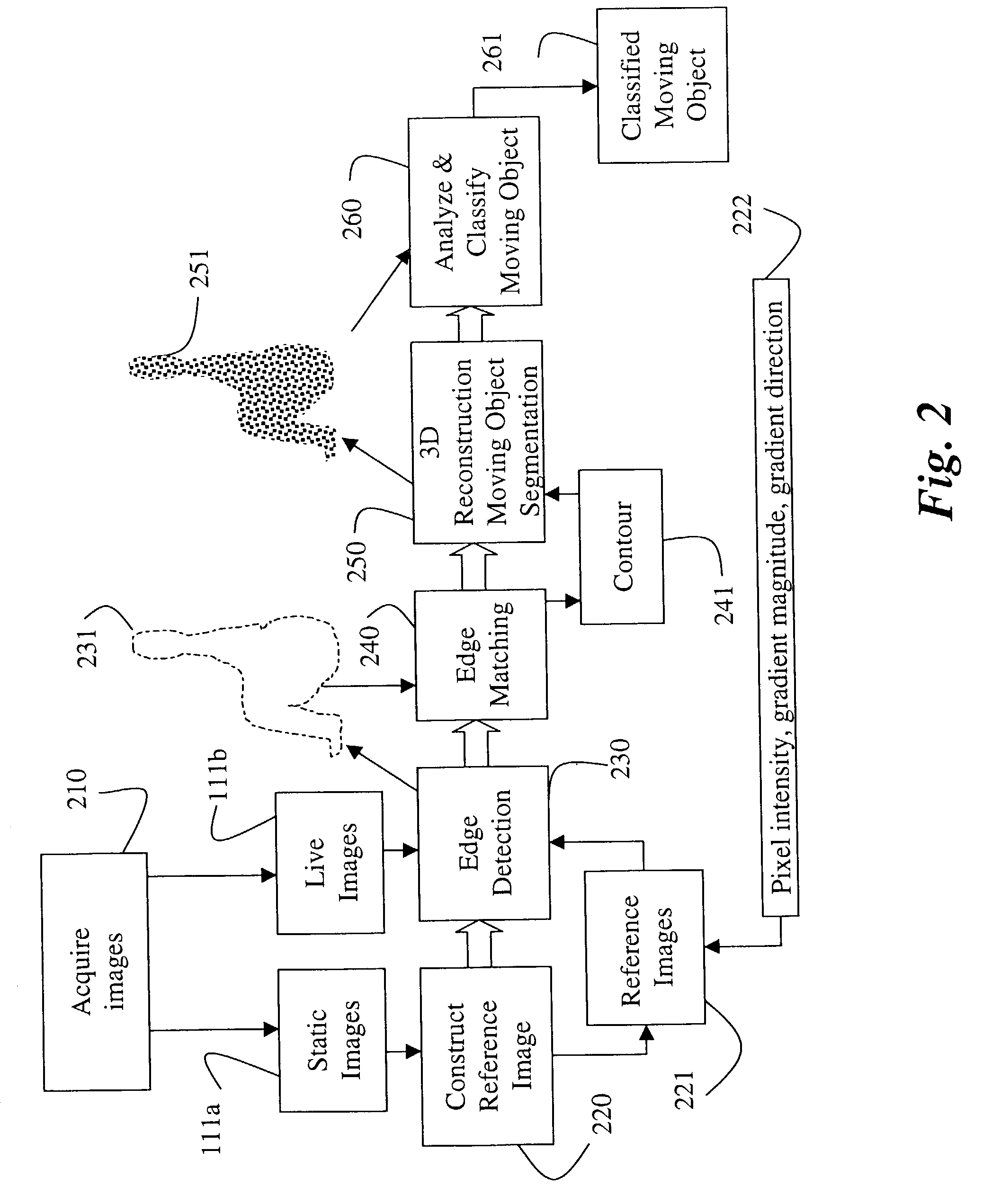
A method detects edges of an object in a scene by first acquiring a static image of the scene when the scene is static, and a live image of the scene including the object. A reference image is constructed from the static image. Then, image gradients of the reference image are compared with image gradients of the live image to identify edges of the object in the live image.

Description

FIELD OF THE INVENTION[0001]The invention relates generally to computer vision, and more particularly to detecting edges of an object in an image.BACKGROUND OF THE INVENTION[0002]It is common to use computer vision techniques to analyze images of a scene. A frequent requirement is to analyze images that vary dynamically over time. For example, in many applications, it is desired to determine whether an object such as a person has appeared in the scene.[0003]Computer vision analysis of an object generally requires multiple processing stages. First, the object is segmented from the background. Attributes such as the shape, 3D motion and location of the object can then be determined. Finally, the object can be analyzed for the purpose of classification or recognition.[0004]Frequently, background subtraction is usually to perform segmentation, in the case of a fixed camera observing an object appearing in front of a static background. Conventional background subtraction methods are base...

Claims


Application Information

Patent Timeline
Patent Type & Authority Patents(United States)
IPC IPC(8): G06K9/48G06K9/00G06T5/00
CPCG06K9/00362G06T7/0075G06T7/0083G06T7/2033G06T7/0097G06T2207/30236G06T2207/10021G06T2207/20224G06T7/593G06T7/12G06T7/174G06T7/246G06V40/10
Inventor BEARDSLEY, PAUL
Owner MITSUBISHI ELECTRIC RES LAB INC
Learn More