
System, method and apparatus for coherent optical OFDM

a coherent optical and optical transmission technology, applied in the field of optical transmission systems, can solve the problems of polarization-mode dispersion transmission impairment, large pmd, and large residual cd for optical communication

Active Publication Date: 2012-07-10
RPX CORP
View PDF13 Cites 34 Cited by
  • Summary
  • Abstract
  • Description
  • Claims
  • Application Information

AI Technical Summary

Benefits of technology

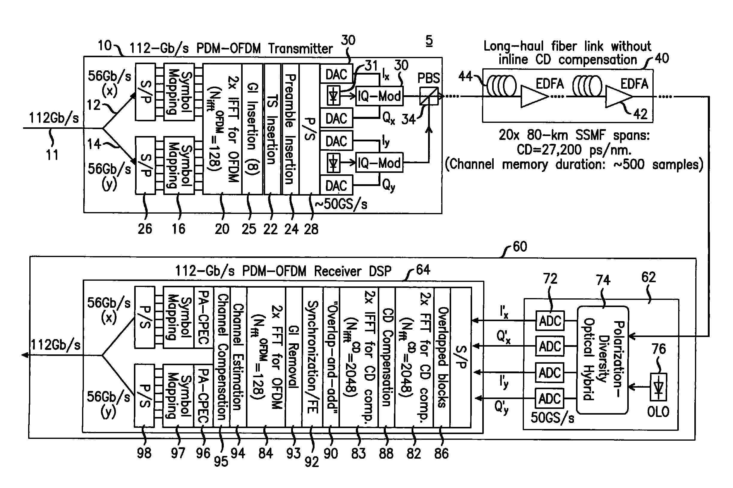
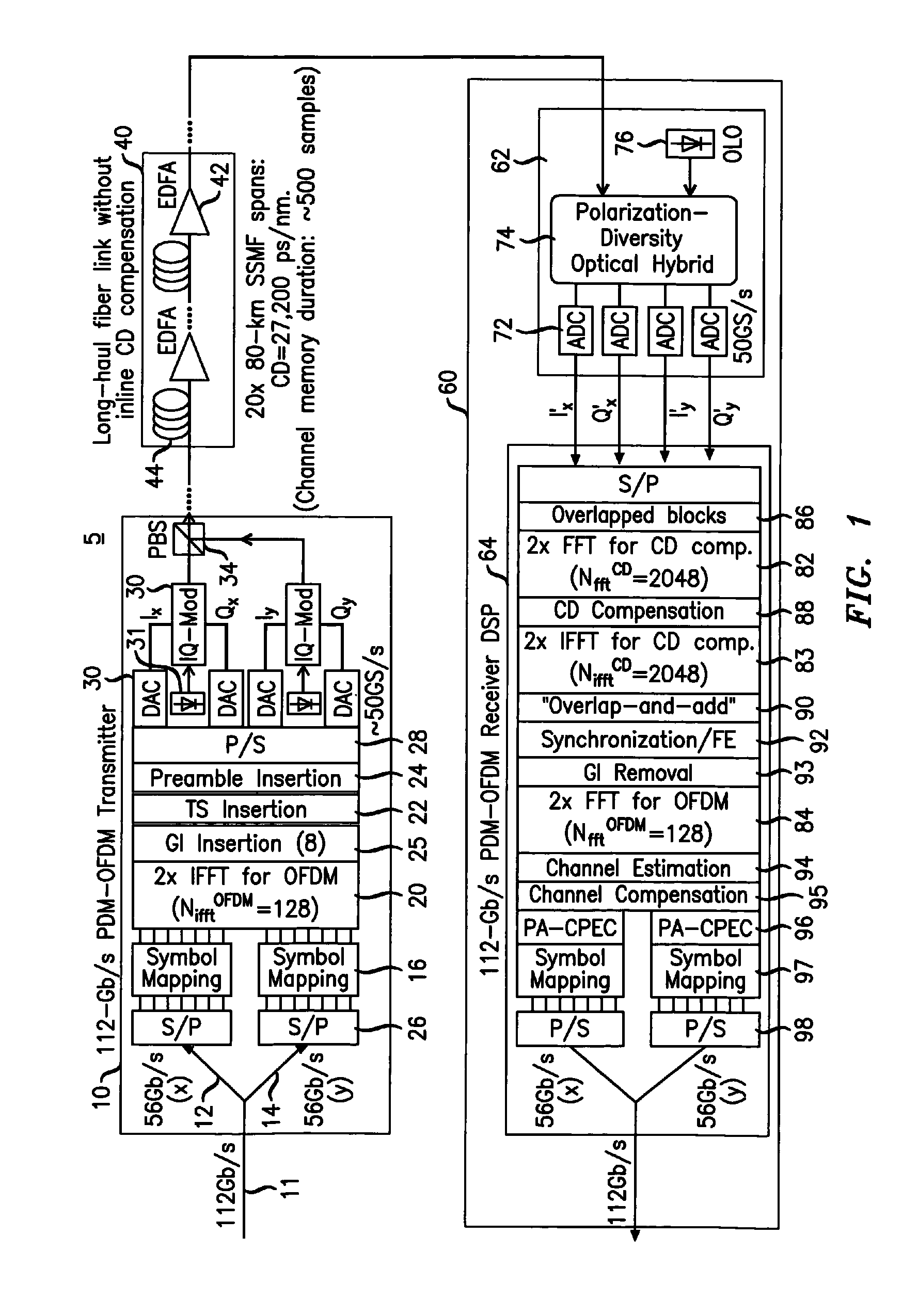
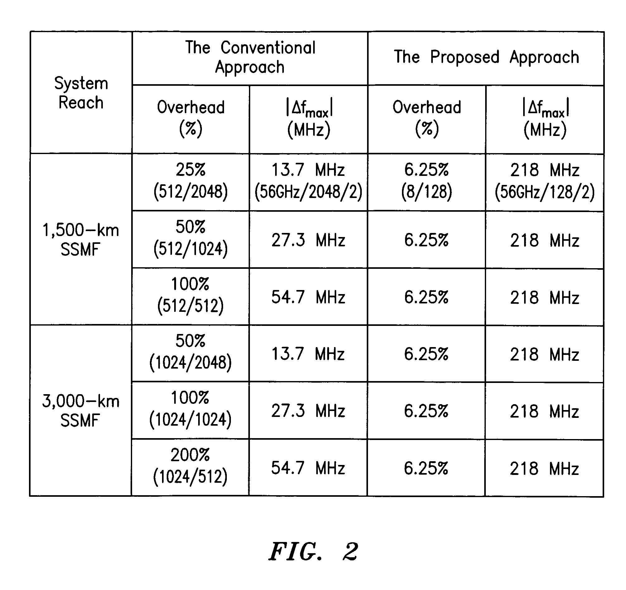
[0010]In OFDM receiver, it is desired to control the OLO frequency to be within half of the OFDM subcarrier spacing away from the transmitter laser frequency to facilitate frequency estimation. Thus, it is desired to make the OFDM subcarrier spacing as large as possible to ease the frequency stabilization task. In one embodiment, the equal length is 2N times as long as the length of the FFT used for OFDM subcarrier demultiplexing, wherein N is a positive integer. The length of the FFT used for OFDM subcarrier demultiplexing, NfftOFDM, is chosen to satisfy the condition NfftOFDM<fsRX / (100 MHz), where fsRX is a sampling frequency at which the digital samples are sampled. This condition assures that the OFDM subcarrier spacing (fsRX / NfftOFDM) is >100 MHz, so that the allowable range of laser frequency offset between the transmitter laser and the OLO is at least [−50 MHz, 50 MHz]. This makes the practical realization of laser frequency stabilization feasible.
[0016]In an embodiment, the OFDM transmitter may include a guard-interval (GI) insertion module configured to allocate a guard-interval (GI) that is at least 10 times shorter than the length of the IFFT module used for OFDM subcarrier multiplexing. In one embodiment, the length of the FFT used for OFDM subcarrier demultiplexing, NfftOFDM, satisfies NfftOFDM<fsRX / (100 MHz), where fsRX is a sampling frequency at which the digital samples are sampled. Likewise, the length of the IFFT used for OFDM subcarrier multiplexing, NifftOFDM, may satisfies the condition NifftOFDM<fsTX / (100 MHz), where fsTX is the sampling frequency of the digital-to-analog converter (DAC) used in the OFDM transmitter. This condition assures that the allowable range of laser frequency offset between the transmitter laser and the OLO is at least [−50 MHz, 50 MHz]. This makes the practical realization of laser frequency stabilization feasible.

Problems solved by technology

At 40 Gb / s and beyond, even after the application of DCF the residual CD may still be too large for feasible optical communication.
Another transmission impairment experienced in CO-OFDM transmission is Polarization-Mode Dispersion (PMD), which is a stochastic characteristic of optical fiber due to imperfections in production and installation.
Newer fibers have a PMD lower than 0.1 ps / √km, but other optical components in a fiber link such as reconfigurable add / drop multiplexers (ROADMs) may cause substantial PMD.
If 40 Gb / s systems are to be operated over the older fiber links or over new fiber links with many ROADMs, PMD may become a significant detriment.
However, due to the statistical nature of PMD with fast variation speeds up to the few kHz range, the realization of optical PMD compensators is challenging.
With increases in channel data rate, optical signal is more and more limited by the transmission impairments in optical fiber, such as by CD and PMD.
The insertion of large GI between adjacent OFDM symbols to accommodate large CD leads to substantial reduction of transmission spectral efficiency (SE) when the GI becomes a large fraction of the OFDM symbol length.
One obvious way to solve this problem is to proportionally increase the OFDM symbol length so the overhead due to the GI remains low, however, this leads to proportionally large reduction in the frequency spacing between OFDM subcarriers, which in turn leads to unacceptably high requirement on the optical frequency locking between the transmitter laser and the receiver optical local oscillator (OLO).

Method used


Image

  • System, method and apparatus for coherent optical OFDM
  • System, method and apparatus for coherent optical OFDM
  • System, method and apparatus for coherent optical OFDM

Examples


Embodiment Construction

[0020]Various example embodiments will now be described more fully with reference to the accompanying figures, it being noted that specific structural and functional details disclosed herein are merely representative for purposes of describing example embodiments. Example embodiments may be embodied in many alternate forms and should not be construed as limited to only the embodiments set forth herein.

[0021]It will be understood that, although the terms first, second, etc. may be used herein to describe various elements, these elements should not be limited by these terms since such terms are only used to distinguish one element from another. For example, a first element could be termed a second element, and, similarly, a second element could be termed a first element, without departing from the scope of example embodiments. As used herein, the term “and” is used in both the conjunctive and disjunctive sense and includes any and all combinations of one or more of the associated list...


PUM


Abstract

Digital compensation of chromatic dispersion (CD) effect experienced by optical orthogonal frequency-division multiplexed (OFDM) signal in fiber transmission is provided in the frequency domain using a Fast Fourier Transform / Inverse Fast Fourier Transform (FFT / IFFT) pair with equal length of digital samples prior to OFDM receiver signal processing, wherein the equal length is larger than the length of a FFT used for OFDM subcarrier demultiplexing of the received signal. The OFDM signal processing is independent of fiber CD, so small guard-interval (GI) can still be used to achieve high spectral efficiency even under the experience of large CD. The GI need only to be large enough to accommodate other effects such as polarization-mode dispersion. The length of an IFFT used for OFDM subcarrier multiplexing, as well as the FFT for OFDM demultiplexing can be sufficiently small so subcarrier spacing is sufficiently large to tolerate typical frequency offsets between the transmitter laser and the optical local oscillator.

Description

FIELD OF THE INVENTION[0001]The invention relates to optical transmission systems, and, in particular, to systems, apparatuses and techniques for compensation of fiber dispersion in coherent optical orthogonal frequency-division multiplexing (CO-OFDM) systems.BACKGROUND INFORMATION[0002]Orthogonal frequency-division multiplexing (OFDM) is a widely used digital modulation / multiplexing technique. Coherent optical orthogonal frequency-division multiplexing (CO-OFDM) is being considered as a promising technology for future high-speed (e.g., 100-Gb / s per-channel data rate) optical transport systems. In high-speed long-haul optical fiber transmission based on CO-OFDM, large guard-interval (GI) between adjacent OFDM symbols is needed to accommodate fiber chromatic dispersion (CD) induced inter-symbol interference (ISI).[0003]Chromatic dispersion (CD) is a deterministic distortion given by the design of the optical fiber. It leads to a frequency dependence of the optical phase and its effec...

Claims


Application Information

Patent Timeline
Patent Type & Authority Patents(United States)
IPC IPC(8): H04B10/06
CPCH04B10/2513H04L27/2697H04B10/548H04J14/002
Inventor LIU, XIANG
Owner RPX CORP
Learn More