

Peritoneal dialysis method
a peritoneal dialysis and dialysis technology, applied in the field of peritoneal dialysis, can solve the problems of patients' death and achieve the effect of less peritoneal injuries
- Summary
- Abstract
- Description
- Claims
- Application Information
AI Technical Summary
Benefits of technology
Problems solved by technology
Method used
Image

Examples
example 1
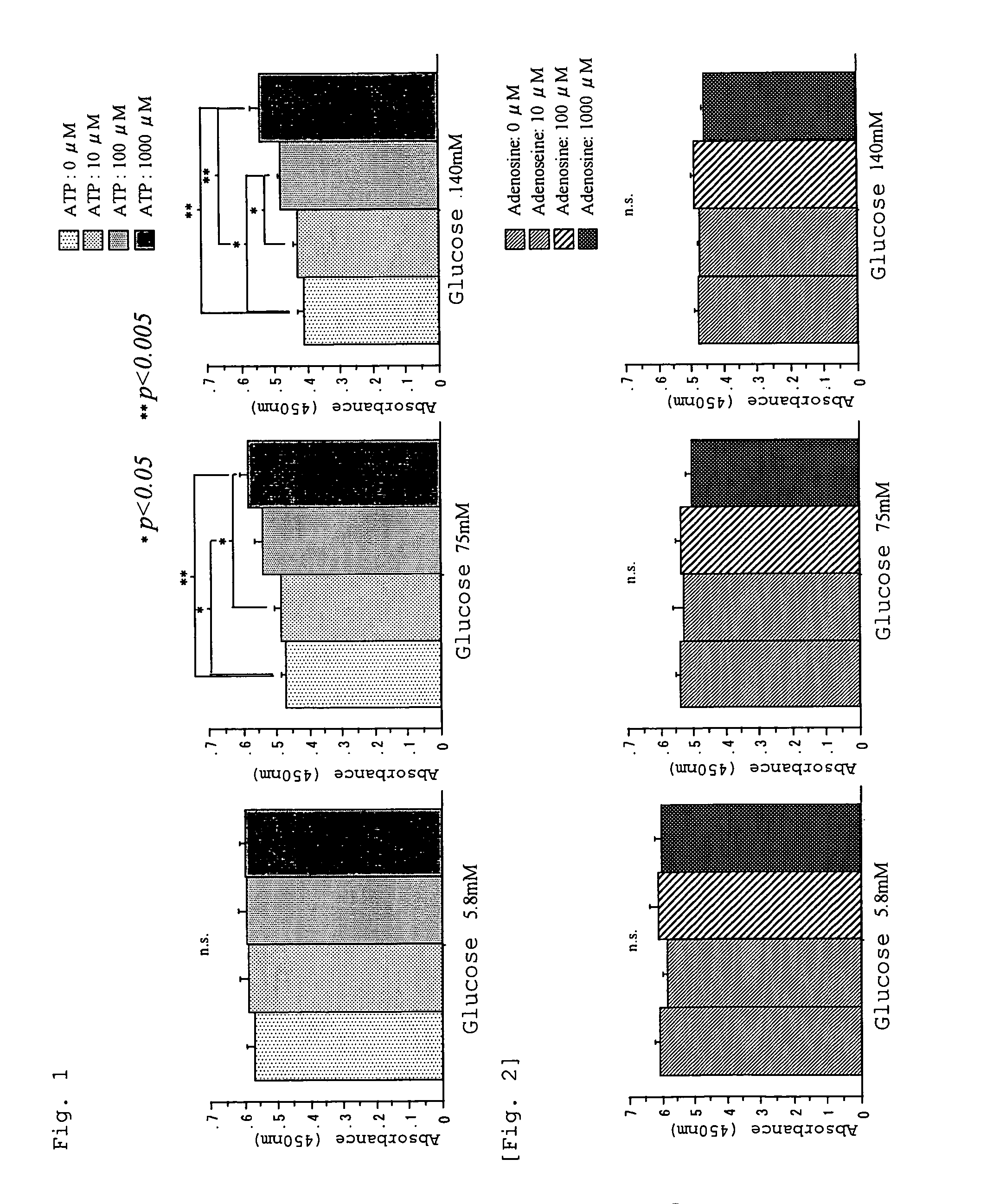
[0033]Peritoneal mesothelial cells (HPMC) were preincubated for three hours in culture media (M199) containing ATP (0, 10, 100, and 1,000 μM). The cells were washed with an HPMC culture medium (saline buffer) and then incubated for eight hours in culture media (M199) containing glucose at three different levels (5.8 mM, 75 mM, and 140 mM). HPMC viability was obtained through cell counting (WST-1).
[0034]The results are shown in FIG. 1. When HPMC was preincubated with the culture media containing no ATP, the viability of the HPMC decreased as the glucose level increased, whereas when HPMC was preincubated with the culture media containing ATP, decrease in viability caused by high level glucose was significantly alleviated.
example 2
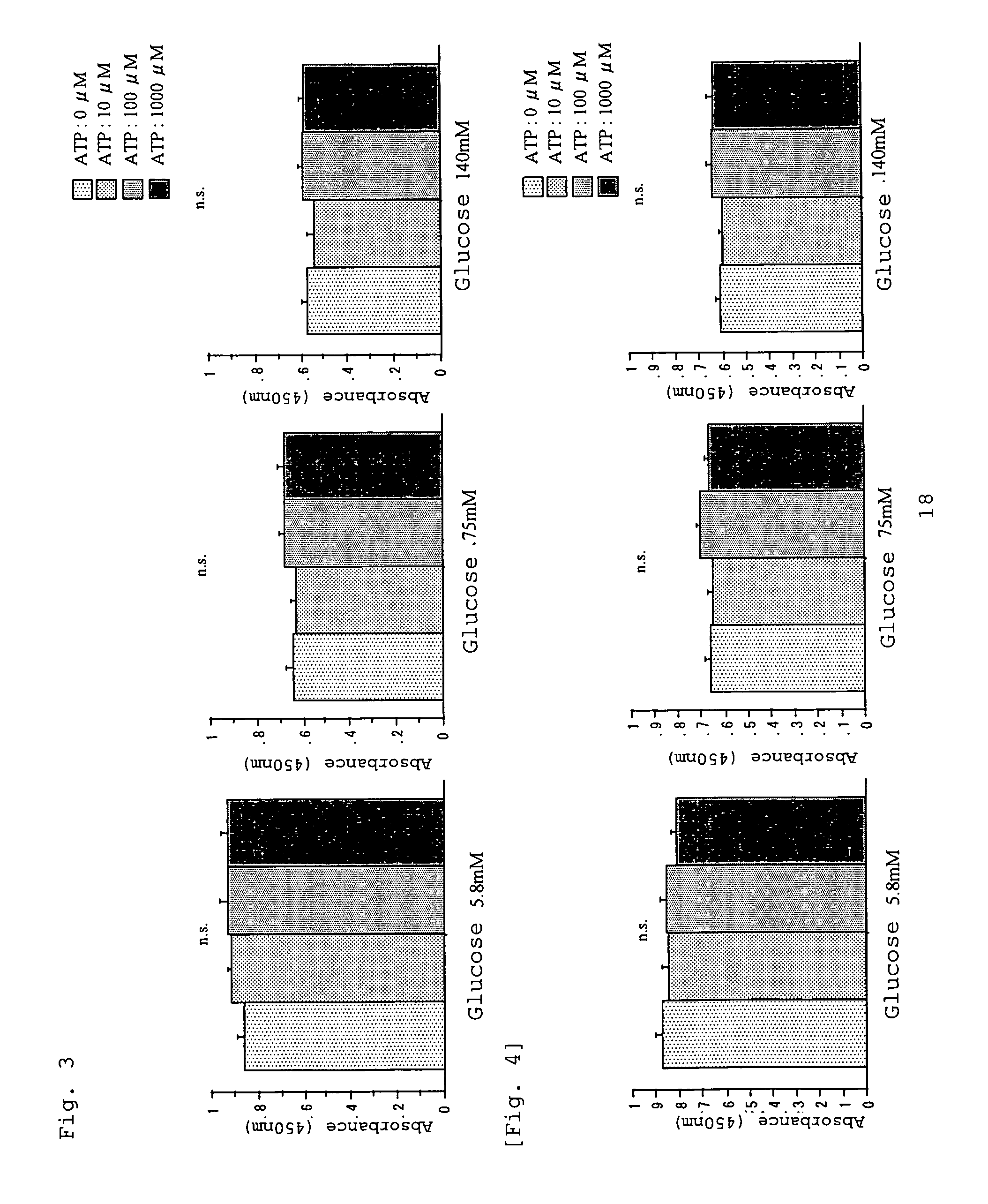
[0035]Instead of ATP, adenosine, which is a metabolite of ATP, was employed to study the effect of adenosine on decrease in HPMC viability caused by high level glucose.
[0036]The results are shown in FIG. 2. Adenosine exhibited no effect of alleviating decrease in HPMC viability, as shown in the case of ATP.
example 3
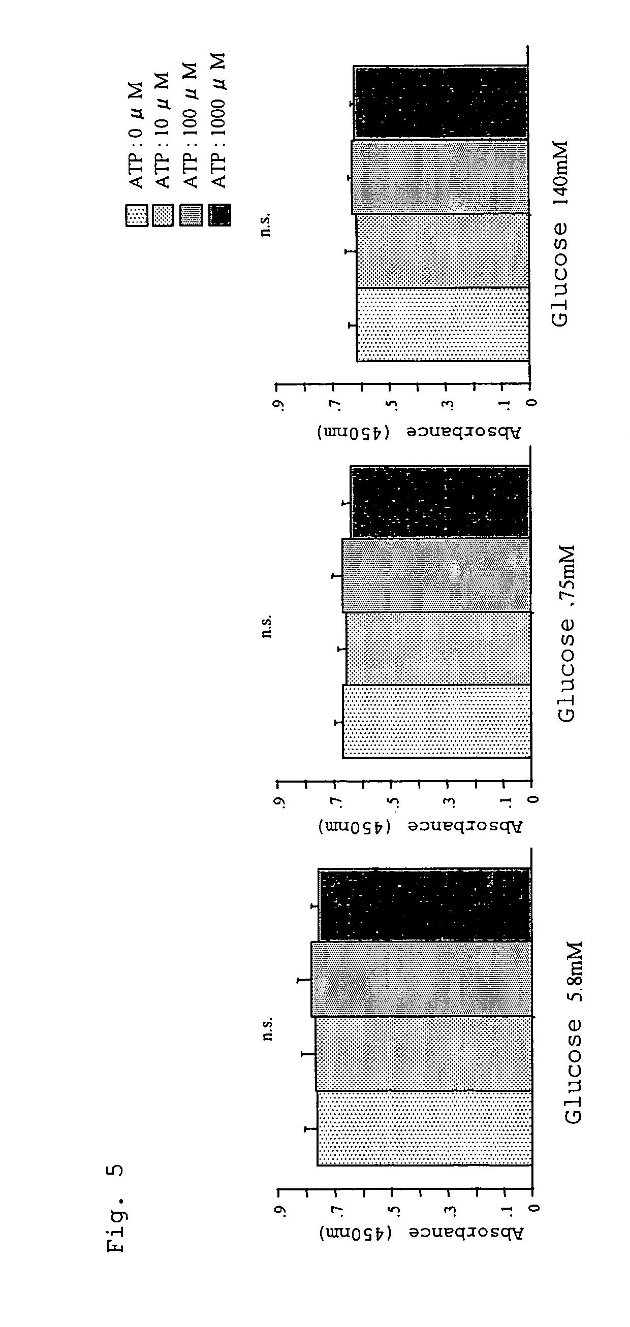
[0037]Prior to the step of preincubation with ATP-containing culture media in the procedure of Example 1, HPMC were preincubated for 30 minutes with each of the following selective ATP receptor antagonists: (1) Suramin (P2X, P2Y receptor antagonist; 10 μM), (2) Reactive Blue 2 (P2Y receptor antagonist; 30 μM), and (3) PPADS (P2X receptor antagonist; 10 μM). Thereafter, the test was performed as described in Example 1.
[0038]The results are shown in FIGS. 3, 4, and 5. When the HPMC was treated with ATP receptor antagonist, ATP exhibited no effect of alleviating reduction in HPMC viability.
[0039]The results obtained in Example 1 indicate that ATP has an effect of significantly preventing peritoneal mesothelial cell injuries caused by high glucose level. The results obtained in Examples 2 and 3 reveal that this effect of ATP is not attributed to an action of ATP serving as an energy source after being taken into the cells, but rather to a direct action of ATP exhibited by the mediation ...
PUM
 Abstract
Description
Claims
Application Information