
Implantable cerebral spinal fluid flow device and method of controlling flow of cerebral spinal fluid

a technology of cerebral spinal fluid and flow control device, which is applied in the direction of intravenous devices, wound drains, etc., can solve the problems of neurological damage, too much drainage, and inability to re-absorb cerebral spinal fluid at the proper ra

Inactive Publication Date: 2006-11-02
MEDTRONIC INC
View PDF25 Cites 15 Cited by
  • Summary
  • Abstract
  • Description
  • Claims
  • Application Information

AI Technical Summary

Benefits of technology

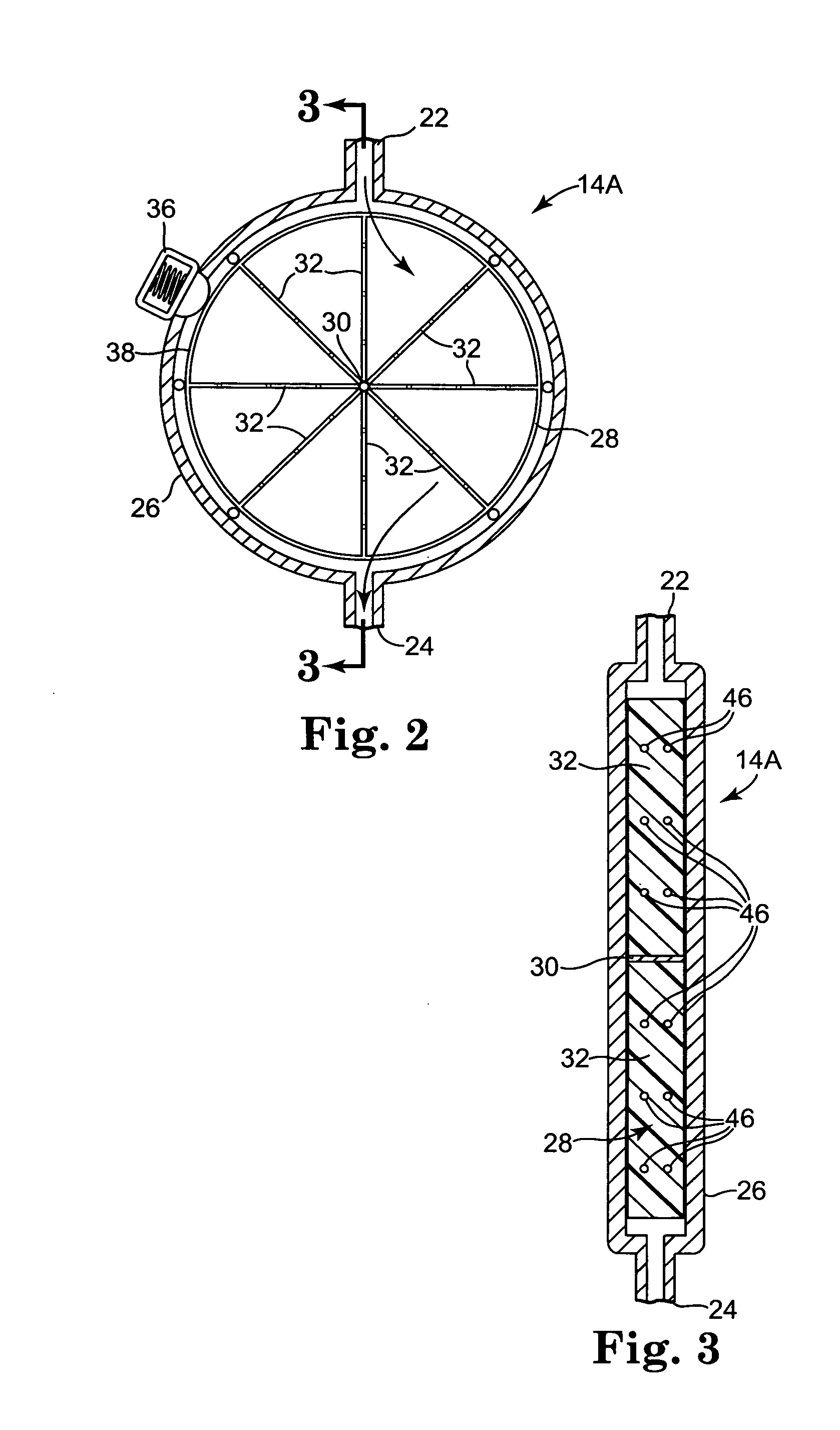
[0011] A reliable device and method for cerebral spinal fluid shunting from the ventricles of the brain alleviates both the problem over drainage due to lack of fluid flow control as well as the problem of reliability. In an embodiment, a rotational element, preferably a pinwheel valve, avoids the use of tiny, restrictive or tortuous passages to control cerebral spinal fluid flow that can become clogged with debris. A braking mechanism can be associated with the rotational element to provide control of cerebral spinal fluid flow.
[0013] Further, a quantitative measurement of the amount of flow of cerebral spinal fluid can easily be obtained by measuring the rotational speed of the rotational element, e.g., pinwheel, and performing a simple arithmetic calculation. A quantitative measurement can be important because the current flow rate can be compared with a baseline of flow rate established at or near the time of implantation, or another prior time, to possibly predict impending shunt failure. The potential ability to predict shunt failure could allow safer, non-emergency revisions and result in less neurological deficit and / or injury to patients.

Problems solved by technology

However, if blockages in circulation of cerebral spinal fluid, perhaps in the ventricles, cerebral spinal fluid can't be reabsorbed by the body at the proper rate.
If left untreated, the increased intracranial pressure can lead to neurological damage and may result in death.
Differences in pressure due, at least in part, to differences in vertical position between the inlet (ventricles) and the outlet (peritoneum) can create too much drainage with such a flow or pressure regulating valve.
Over drainage can lead to slit ventricles, slit ventricle syndrome, loss of brain compliance, shunt occlusion, sub-dural hematoma and many other complications.
Some shunt valves are also prone to becoming clogged.
A clogged shunt valve could result in serious complications through a failure to provide proper drainage of cerebral spinal fluid from the ventricles of the brain.
Another problem facing a medical professional when dealing with cerebral spinal fluid shunting devices and methods is determining whether or not the shunt is working, i.e., whether the shunt is still providing cerebral spinal fluid drainage and, possibly, at what flow rate.
One technique for determining if cerebral spinal fluid flow is present involves the injection of a contrast agent into the cerebral spinal fluid system following by several imaging sessions to monitor clearance of the contrast media, a procedure generally referred to as “shuntogram.” The procedure is generally time consuming, invasive and expensive.
Further, if a patient is in critical condition, time may not be available to allow for the performance of a “shuntogram.”

Method used


Image

  • Implantable cerebral spinal fluid flow device and method of controlling flow of cerebral spinal fluid
  • Implantable cerebral spinal fluid flow device and method of controlling flow of cerebral spinal fluid
  • Implantable cerebral spinal fluid flow device and method of controlling flow of cerebral spinal fluid

Examples


Embodiment Construction

[0049] Consistent and reliable drainage of cerebral spinal fluid from one area of the body to another, e.g., from a ventricle or ventricles of the brain to another region of the body such as the peritoneum pr sagittal sinus, can be desirable. A consistent and reliable drainage method and system can minimize the expense as well as trauma and inconvenience to the patient associated with cerebral spinal fluid revision surgery and can also lesson risk to the patient due to an inoperative cerebral spinal fluid drainage system.

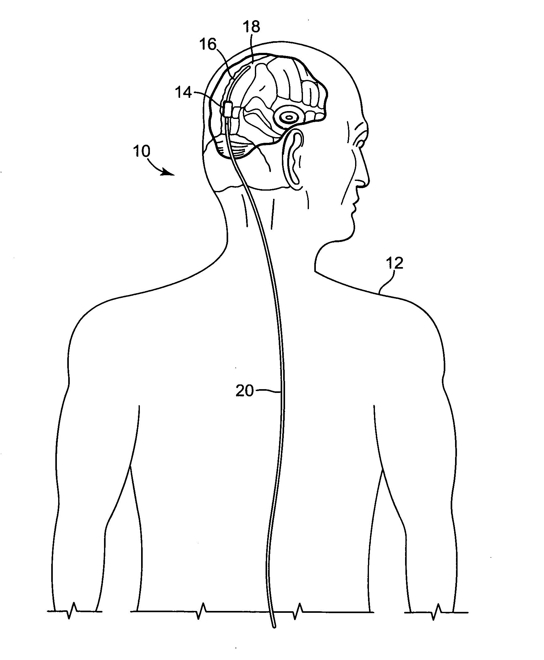
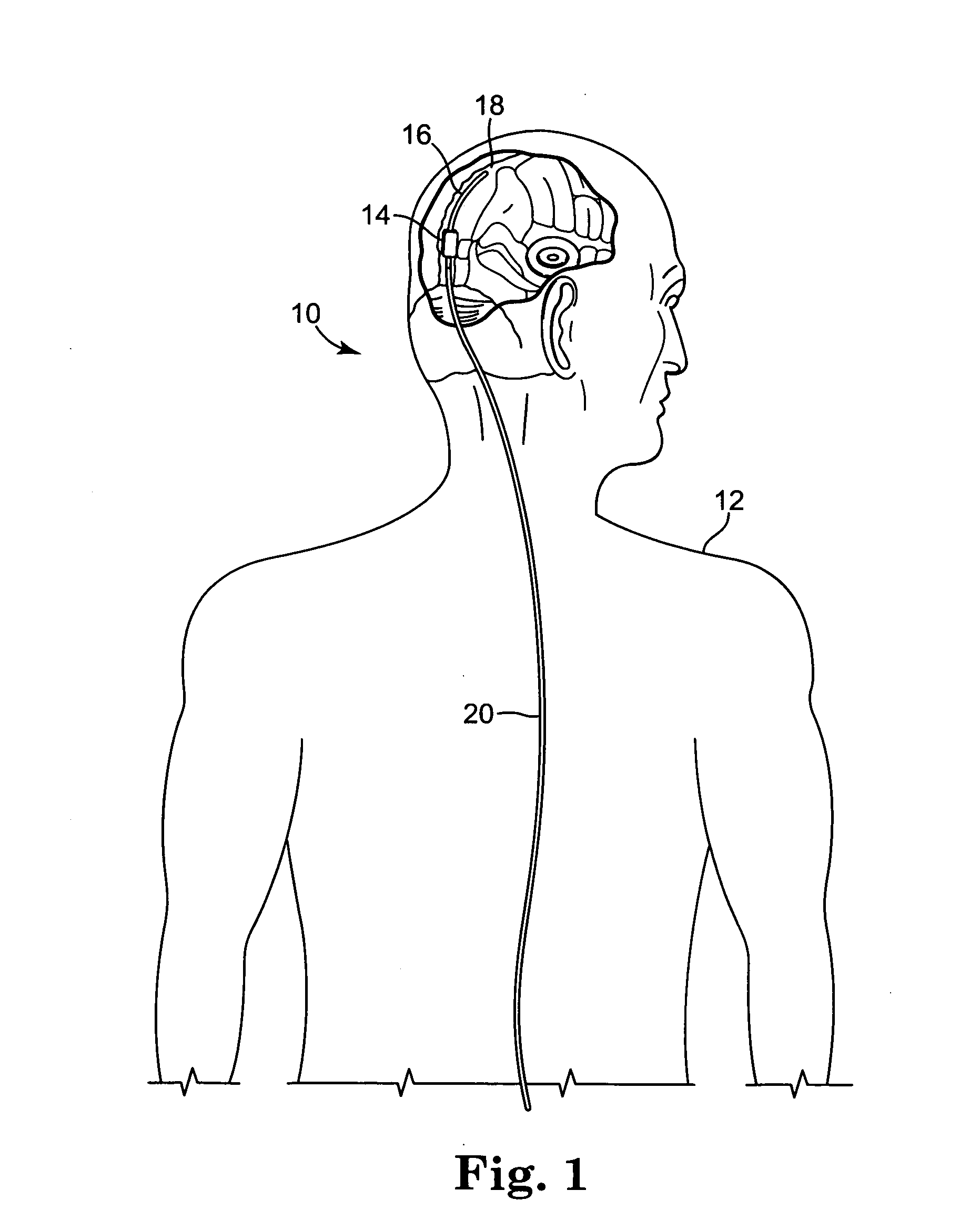
[0050]FIG. 1 illustrates an embodiment of a cerebral spinal fluid shunt, or drainage, system 10 for draining cerebral spinal fluid from one area, preferably the ventricles of brain, of the body of patient 12 to another area of the body of patient 12. Cerebral spinal fluid can preferably be drained to the peritoneum and / or atrium and, alternatively, to the sagittal sinus. Shunt system 10 may consist solely of a catheter having a lumen to transport cerebral spinal fl...


PUM


Abstract

An implantable cerebral spinal fluid flow device and method. A body has an inlet for the cerebral spinal fluid, an outlet for the cerebral spinal fluid and a first interior cavity fluidly coupled with the inlet and the outlet. A first rotational element is mounted in the first interior cavity in a pathway between the inlet and the outlet. The first rotational element provides resistance to flow of the cerebral spinal fluid from the inlet to the outlet. In the method, the cerebral spinal fluid flow device is implanted. Resistance to rotation of the first rotational element to flow of the cerebral spinal fluid from the inlet to the outlet is provided.

Description

FIELD OF THE INVENTION [0001] This invention relates generally to implantable fluid flow control devices and methods and, more particularly, to such devices and methods for controlling flow of cerebral spinal fluid. BACKGROUND OF THE INVENTION [0002] Ventricles of the brain contain cerebrospinal fluid which cushions the brain against shock. Cerebral spinal fluid is constantly being secreted and absorbed by the body usually in equilibrium. Cerebral spinal fluid is produced in the ventricles of the brain, where under normal conditions, it is circulated in the subarachnoid space and reabsorbed into the bloodstream, predominantly via the arachnoids villi attached to the superior sagittal sinus. However, if blockages in circulation of cerebral spinal fluid, perhaps in the ventricles, cerebral spinal fluid can't be reabsorbed by the body at the proper rate. [0003] This can create a condition known as hydrocephalus which is a condition marked by an excessive accumulation of fluid violating...

Claims


Application Information

Patent Timeline
Patent Type & Authority Applications(United States)
IPC IPC(8): A61M5/00
CPCA61M27/006
Inventor BERTRAND, WILLIAM J.SUGLERIS, WILLIAM
Owner MEDTRONIC INC
Learn More