Dynamic arch stabilization and rehabilitative shoe midsole/insole device

a technology of dynamic arch stabilization and shoe midsole, which is applied in the field of shoe midsole/insole device, can solve the problems of overly high arch height, affecting the comfort of users, and a large number of users who find the device too uncomfortable to use, so as to achieve the lowest degree of injury inducing stress, optimize the force management, and optimize the effect of muscular energy

Inactive Publication Date: 2013-12-05
GARDINER ROY
View PDF12 Cites 14 Cited by
  • Summary
  • Abstract
  • Description
  • Claims
  • Application Information

AI Technical Summary

Benefits of technology

[0016]The resilient ellipsoidal or spherically shaped biofeedback catalysts display physical properties as to dynamically stimulate the body's natural neuromuscular reflex mechanisms that effectively optimally align and stabilize the foot's musculoskeletal arch system and ankle. The plantar aspect of the ellipsoidal and spherically shaped biofeedback catalysts encourages the catalysts to dynamically roll and pivot about their plantar apexes as they mirror the foot's movement through multidimensional activities. This dynamic movement ensures that the ellipsoidal and spherically shaped biofeedback catalysts' dorsal aspect a

Problems solved by technology

The catalyst is an asymmetrically domed hump, which creates a mild to strong discomfort to initially stimulate the Golgi tendon organ.
However, it has been found that the device disclosed in U.S. Pat. No. 5,404,659 does not function as described, and that the majority of users find the device too uncomfortable to use.
A device built according to these dimensions and deflection capabilities results in an overly high arch height, and can cause severe discomfort, and possible injury, to a wearer.
This is clearly wrong, since different wearers will have different comfort thresholds and arch heights.
Users would find the device too hard to use successfully, and rather than stimulating a proprioceptive response, the device would cause pain and discomfort at each step.
However, it has been found that the devices disclosed in U.S. Pat. No. 5,404,659, in U.S. Pat. No. 6,

Method used


Image

  • Dynamic arch stabilization and rehabilitative shoe midsole/insole device
  • Dynamic arch stabilization and rehabilitative shoe midsole/insole device
  • Dynamic arch stabilization and rehabilitative shoe midsole/insole device

Examples


Embodiment Construction

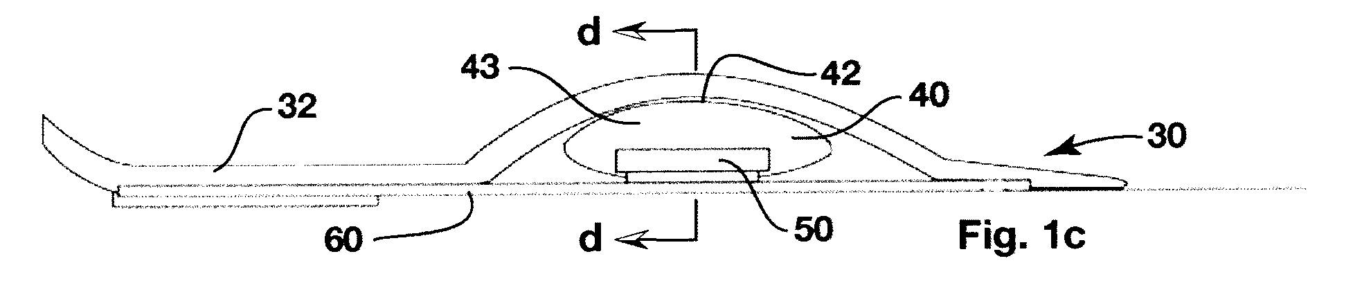
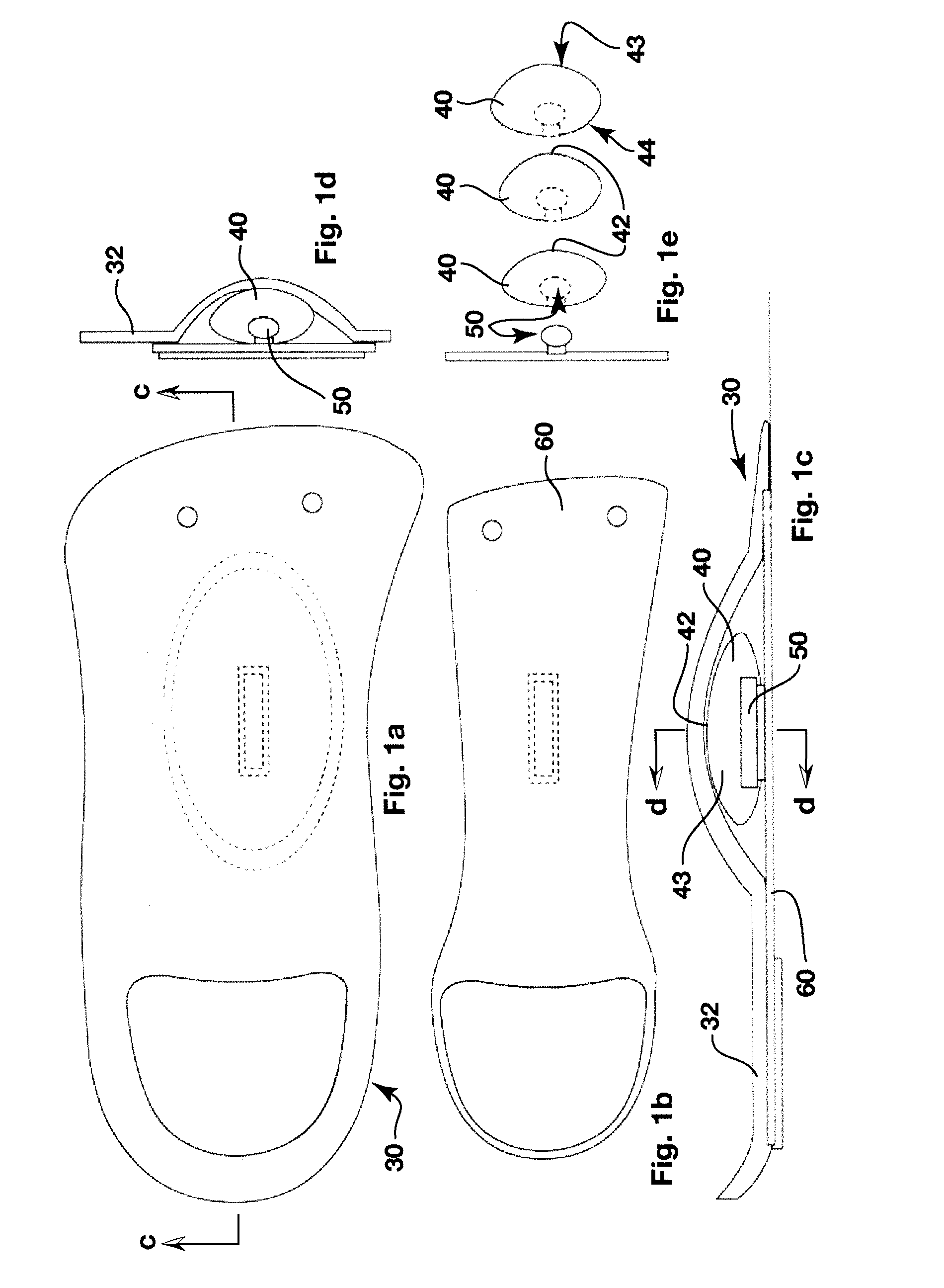
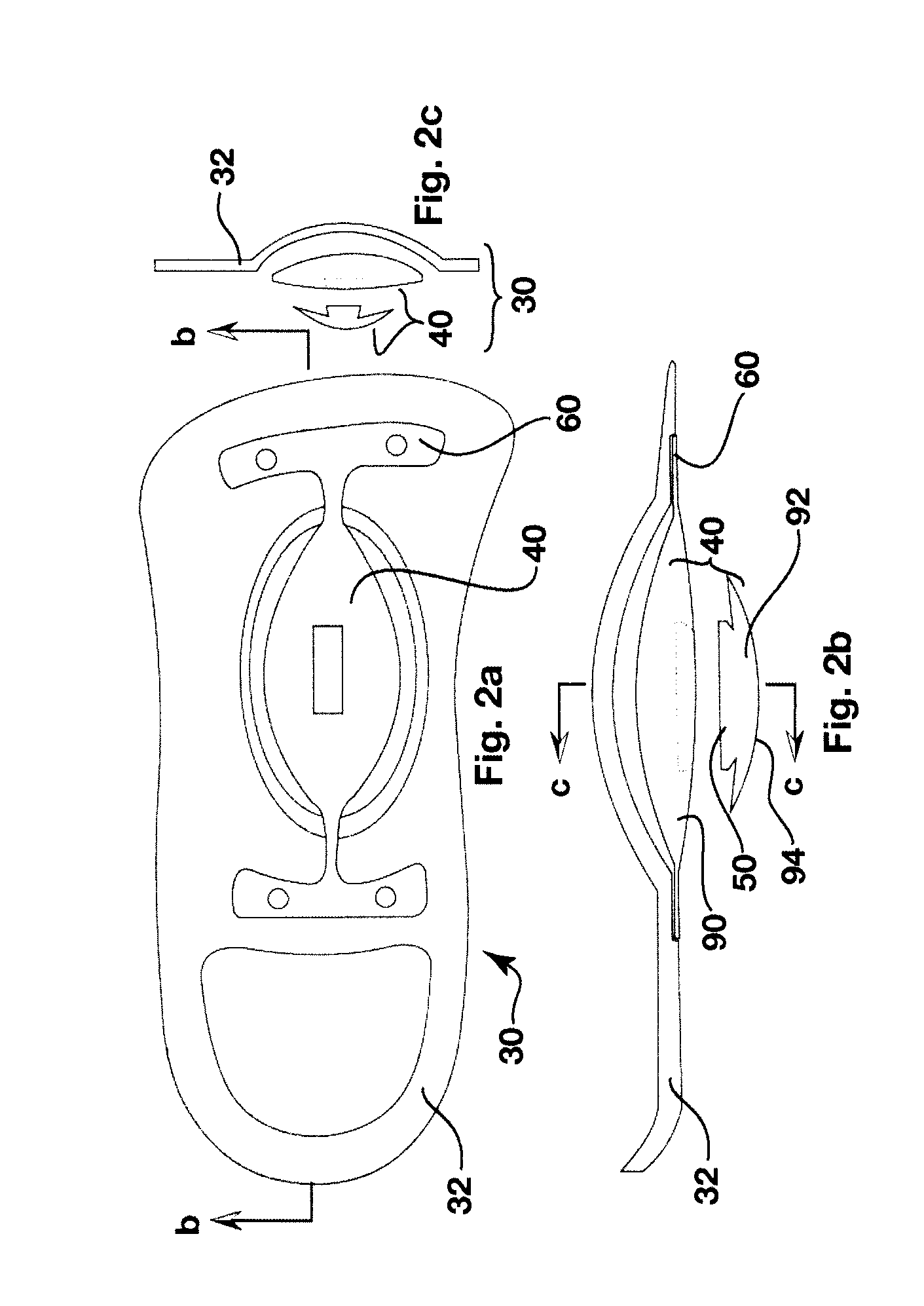
[0091]A dynamic arch stabilization and rehabilitative insole device is generally illustrated by reference 30 in the Figures. The insole device 30 consists of a flexible insole body having an outer portion 32 defining an upwardly extending dome 34 located central to the foot's anatomical arch apex. The dome 34 receives interchangeable substantially ellipsoidal and spherically shaped catalysts 40 for interfacing with the plantar aspect of a human foot.

[0092]The catalysts 40 have an apex 42 on the dorsal surface for aligning with a target area within the foot, the target area being defined by the anatomical arch apex.

[0093]The plantar aspect (bottom) 44 of the catalysts, in concert with the flexible insole body encourage the catalysts to dynamically roll and pivot about their plantar apexes as they mirror the foot's movement through multidimensional activities.

[0094]The catalysts 40 are resiliently deformable to apply an upwardly directed pressure to stimulate the nocioreceptors and me...


PUM


Abstract

An insole device as provided which has a sole shaped body defining an upwardly extending dome in a midfoot section thereof. A biofeedback catalyst is mountable in the dome so as to be moveable at least longitudinally relative to the sole shaped body. The catalyst is positionable to cause the dome to engage an anatomical apex of the sole face of the arch of a wearer's foot. The catalyst has an ellipsoidal or spherical shape, being dimensioned and having a resiliency sufficient to promote dynamic proprioceptive stimulation of mechanical receptors and nocioreceptors in the skin of the wearer's sole at said apex. Cooperating engagement means extend between the body and the catalyst for connecting the catalyst to the body to locate the catalyst in the dome while allowing the movement of the catalyst relative to the body.

Description

[0001]This application claims the benefit of priority from U.S. provisional application no. U.S. 61 / 457,252 filed Feb. 10, 2011, the entire contents of which are incorporated by reference herein.FIELD OF THE INVENTION[0002]The present invention relates to an insole for a shoe. In particular, the present invention relates to an insole device that can rehabilitate a foot by stimulating a proprioceptive reflex response in the wearer's foot.BACKGROUND OF THE INVENTION[0003]Professionals dealing with gait related pathologies generally accept that a large majority of persons will, at some time in their lives, suffer some form of gait related pain or dysfunction. It is also well accepted that, in the majority of cases, the mechanism underlying the pathology, injury, or dysfunction is biomechanically related to the foot's musculoskeletal capabilities during the interface between the foot and the ground, during the initial contact, support, and propulsion phases of the gait cycle.[0004]It ha...

Claims


Application Information

Patent Timeline
IPC IPC(8): A43B13/38
CPCA43B13/38A43B7/141A43B7/142A43B7/148A43B7/149A61F5/14A43B17/00A43B7/1464
Inventor GARDINER, ROY
Owner GARDINER ROY
Why Eureka
Try Eureka