Battery pack

a battery pack and battery technology, applied in the field of battery packs, can solve the problems of increased cost, limited business use of electric power, and power loss, and achieve the effect of convenient handling

Inactive Publication Date: 2012-07-17
SAKAKIBARA KAZUYUKI
View PDF12 Cites 32 Cited by
  • Summary
  • Abstract
  • Description
  • Claims
  • Application Information

AI Technical Summary

Benefits of technology

[0009]In view of the foregoing, it would be preferable to provide a battery pack which can be carried and transported to where the commercial power source is not available, for potential household purposes, which is inexpensive and easy to be handled, and which can output power at a level which is comparable to that of the commercial power source.

Problems solved by technology

For this reason, it is unavoidable to accept a performance drop which results from such as an electric power loss due to the use of a large load current.
Unfortunately, its use is limited to business purposes, because of the lack of ease-to-use, the need for increased costs, etc.

Method used


Image

  • Battery pack
  • Battery pack
  • Battery pack

Examples


Embodiment Construction

[0030]According to the invention, the following modes are provided as illustrative embodiments of the invention:[0031](1) A battery pack usable as a power source for an electric device, comprising:

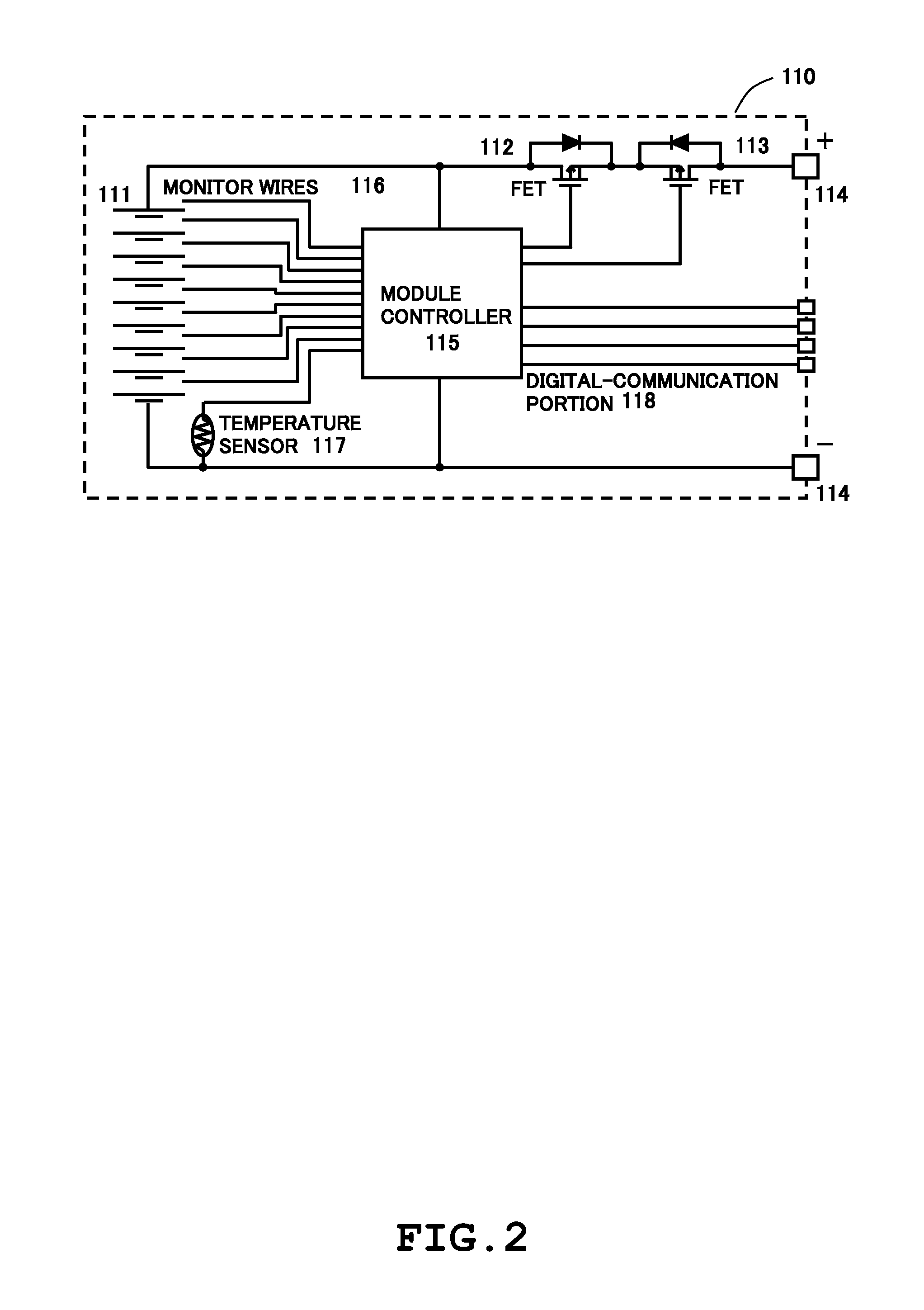
[0032]a battery cell group in which a plurality of battery cells are interconnected in series;

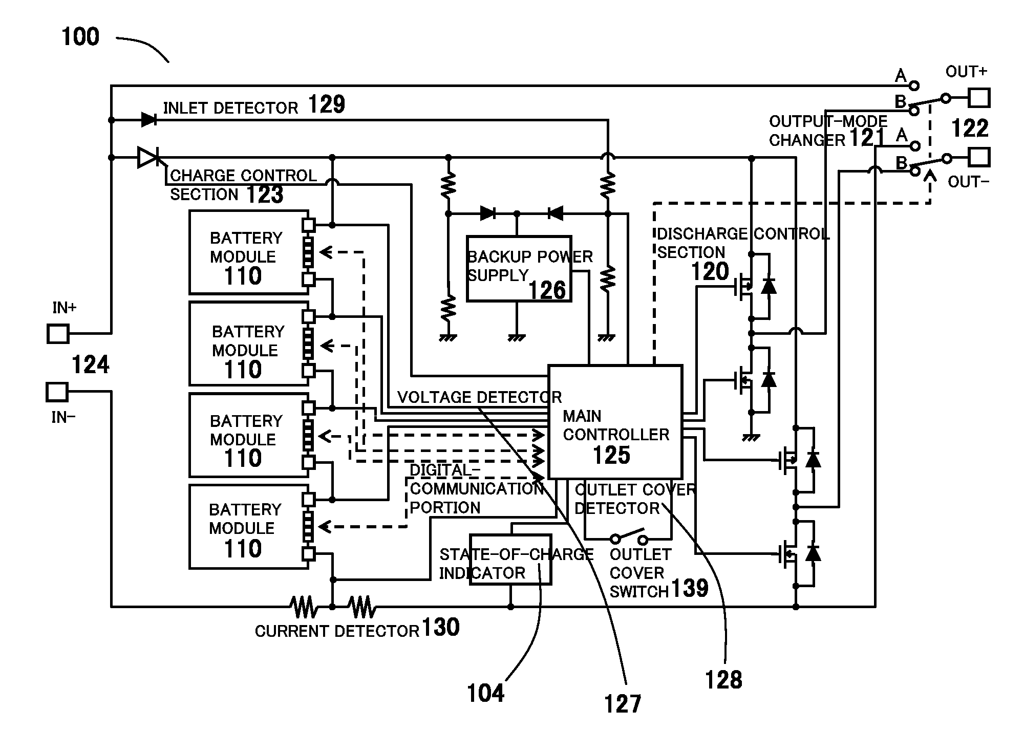
[0033]discharge control circuitry for converting DC voltage of the battery cell group into AC voltage;

[0034]an AC-output terminal through which an output of the discharge control circuitry is supplied to the electric device;

[0035]charge control circuitry for converting AC voltage of a commercial power source into DC voltage, to thereby charge the battery cell group;

[0036]a charging terminal through which electric power of the commercial power source is supplied into the battery cell group; and

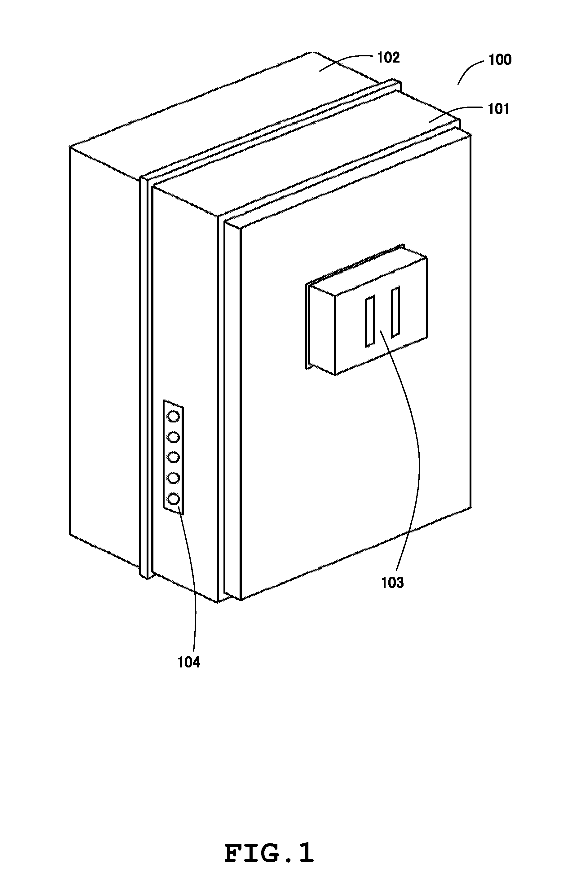
[0037]a case within which the battery cell group, the discharge control circuitry, the AC-output terminal, the charge control circuitry and the charging terminal are housed,

[0038]wherein the AC-output termina...


PUM

PropertyMeasurementUnit
DC voltageaaaaaaaaaa
frequencyaaaaaaaaaa

Abstract

A battery pack for an electric device is disclosed which includes: a group of battery cells interconnected in series; discharge control circuitry for converting DC voltage of the group into AC voltage; an AC-output terminal through which an output of the discharge control circuitry is supplied to the device; charge control circuitry for converting AC voltage of a commercial power source into DC voltage, to thereby charge the group; and a charging terminal through which electric power of the source is supplied into the group, wherein the AC-output terminal is connectable with a power-input connector of the device, and the charging terminal is connectable with a charging connector of the source, the pack further comprising a detector for detecting insertion of the power-input connector into the AC-output terminal, wherein the discharge control circuitry initiates a discharge control sequence for the group, if the insertion is detected, and does not initiate the discharge control sequence, in response to non-detection of the insertion.

Description

RELATED APPLICATIONS[0001]This application is a continuation-in-part filing of International Patent Application No. PCT / JP2008 / 071632, filed Nov. 28, 2008 and published on Jun. 25, 2009 as WO 2009 / 078262, which claims the priority benefit of Japanese Application Serial No. 2007-324416, filed Dec. 17, 2007, the contents of which applications and publication are incorporated herein by reference in their entirety.BACKGROUND OF THE INVENTION[0002]1. Field of the Invention[0003]The present invention relates to battery packs which are constructed with rechargeable batteries such as Li-ion batteries.[0004]2. Description of the Related Art[0005]An electric device is primarily powered by an AC voltage supplied from a commercial power source, or a DC voltage supplied from battery cells. The above-described electric devices using battery cells as a power source include a type of an electric device, as represented by such as a cellular telephone, which specially fits very small load current app...

Claims


Application Information

Patent Timeline
Patent Type & Authority Patents(United States)
IPC IPC(8): H02J7/00H02J7/02H01M50/204H01M50/271H01M50/296H02J9/06
CPCH01M2/1016H01M10/425H01M10/42H01M2/1072Y02E60/10H01M50/204H01M50/296H01M50/271
Inventor SAKAKIBARA, KAZUYUKI
Owner SAKAKIBARA KAZUYUKI
Why Eureka
Try Eureka