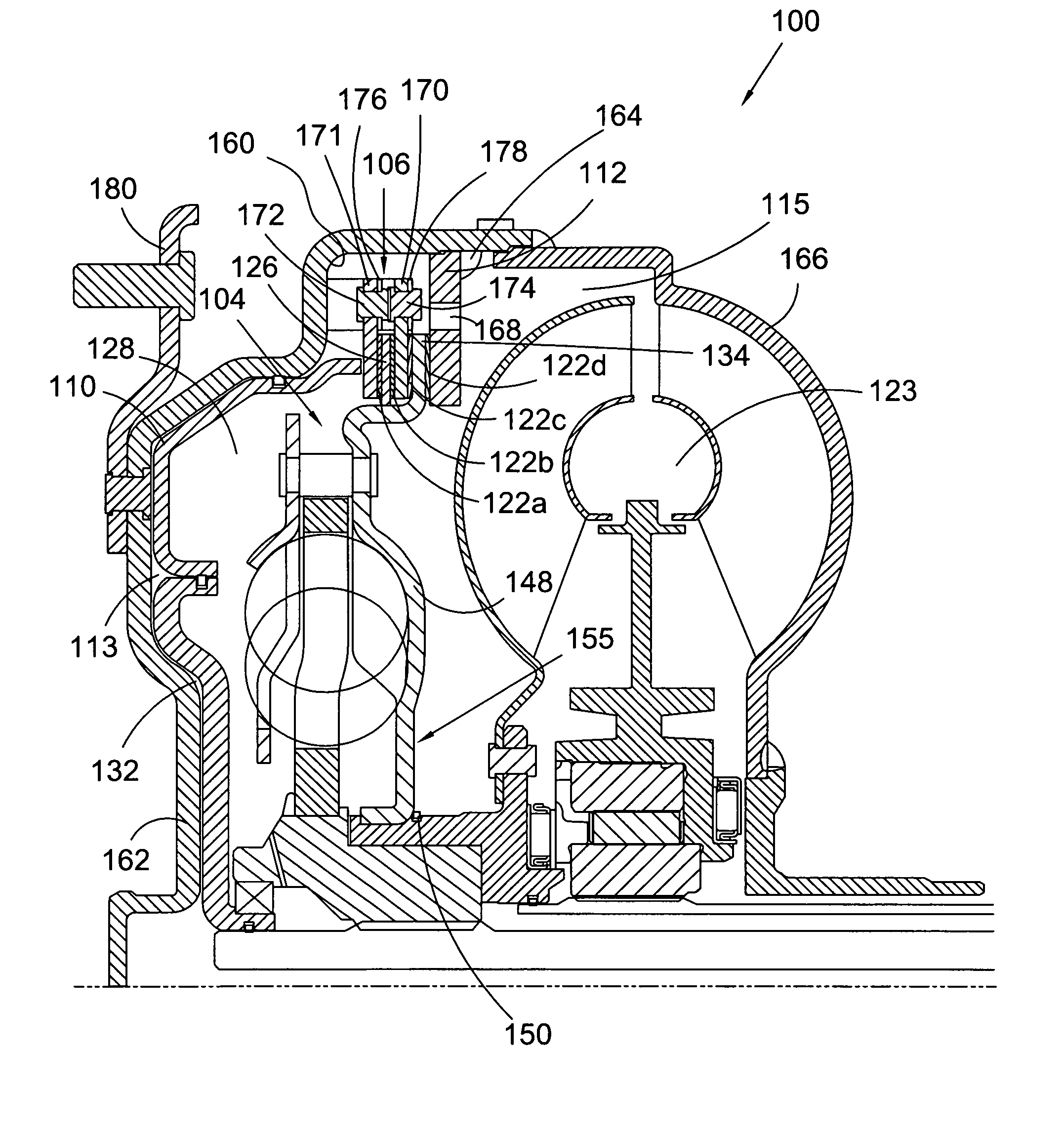
Torque converter with cooling fluid flow arrangement and arrangement for torque transfer to a damper

a technology of torque converter and cooling fluid, which is applied in the direction of fluid couplings, gearings, couplings, etc., can solve the problems of low efficiency of torque converter, limited peak torque converter efficiency of 92-93%, undesirable vibration and noise, etc., to reduce drag in the torque converter clutch, prevent rattle, and improve the effect of cooling flow

Active Publication Date: 2012-07-24
SCHAEFFLER TECH AG & CO KG
View PDF15 Cites 5 Cited by
  • Summary
  • Abstract
  • Description
  • Claims
  • Application Information

AI Technical Summary

Benefits of technology

[0030]It is a general object of the present invention to provide a torque converter with a means of preventing rattle and reducing drag in a torque converter clutch during operation in torque converter mode, while also improving cooling flow.

Problems solved by technology

At speed ratios less than 1, the torque converter is less than 100% efficient.
Peak torque converter efficiency is limited to 92-93% based on losses in the fluid.
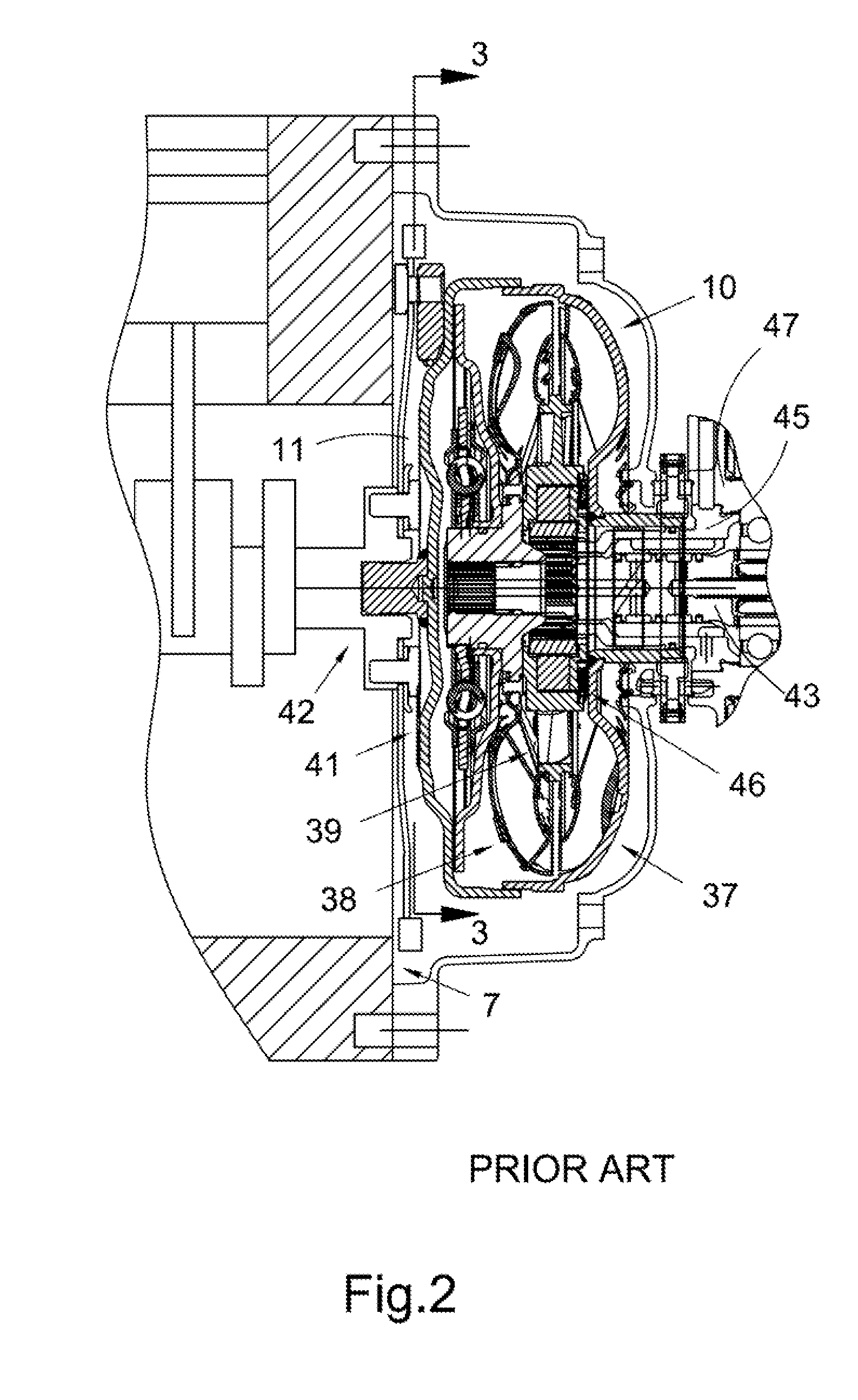
Thus, there is intermittent contact between cover plate 16 and the turbine hub at the at the spline connection between the plate and the hub, resulting in undesirable vibration and noise.

Method used


Image

  • Torque converter with cooling fluid flow arrangement and arrangement for torque transfer to a damper
  • Torque converter with cooling fluid flow arrangement and arrangement for torque transfer to a damper
  • Torque converter with cooling fluid flow arrangement and arrangement for torque transfer to a damper

Examples


Embodiment Construction

[0049]At the outset, it should be appreciated that like drawing numbers on different drawing views identify identical, or functionally similar, structural elements of the invention. While the present invention is described with respect to what is presently considered to be the preferred aspects, it is to be understood that the invention as claimed is not limited to the disclosed aspects.

[0050]Furthermore, it is understood that this invention is not limited to the particular methodology, materials and modifications described and as such may, of course, vary. It is also understood that the terminology used herein is for the purpose of describing particular aspects only, and is not intended to limit the scope of the present invention, which is limited only by the appended claims.

[0051]Unless defined otherwise, all technical and scientific terms used herein have the same meaning as commonly understood to one of ordinary skill in the art to which this invention belongs. Although any meth...


PUM


Abstract

A torque converter including: a membrane forming a portion of a release chamber for the clutch; a friction plate for a torque converter clutch, the plate rotationally connected to a turbine hub and disposed within the release chamber; and a damper element rotationally connected to the turbine hub and to the torque converter clutch. In lock-up mode for the converter, the plate is arranged to transmit torque to the turbine hub. The torque converter includes cooling fluid and a torus and the clutch further comprises friction material and in some aspects, during the lock-up mode, the release chamber is sealed except for a flow of the cooling fluid from the release chamber through the friction material to the torus. The plate includes oppositely disposed first and second radial surfaces and during a torque converter mode for the torque converter, respective pressures on the first and second surfaces are substantially equal.

Description

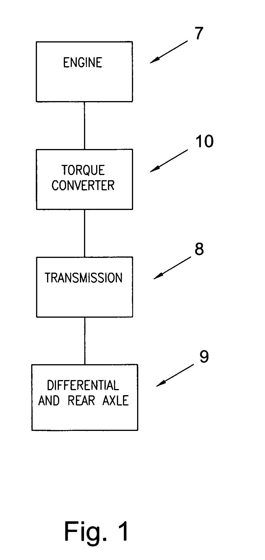
CROSS-REFERENCE TO RELATED APPLICATIONS[0001]This application claims the benefit under 35 U.S.C. §119(e) of U.S. Provisional Application No. 60 / 958,345 filed on Jul. 5, 2007 and U.S. Provisional Application No. 60 / 928,437 filed on May 9, 2007, which applications are incorporated herein by reference.FIELD OF THE INVENTION[0002]The invention relates to improvements in apparatus for transmitting force between a rotary driving unit (such as the engine of a motor vehicle) and a rotary driven unit (such as the variable-speed transmission in the motor vehicle). In particular, the invention relates to a torque converter with a torque converter clutch providing torque to a turbine hub during lock-up mode while minimizing frictional losses during torque converter mode and providing improved cooling flow.BACKGROUND OF THE INVENTION[0003]FIG. 1 illustrates a general block diagram showing the relationship of the engine 7, torque converter 10, transmission 8, and differential / axle assembly 9 in a...

Claims


Application Information

Patent Timeline
Patent Type & Authority Patents(United States)
IPC IPC(8): F16D33/02
CPCF16H45/02F16H2045/0294F16H2045/0284
Inventor LIANG, YANGSWANK, MICHAEL G.JAMESON, JONATHAN G.PARKS, KEVINOLSEN, STEVENHOFFMANN, JOACHIM
Owner SCHAEFFLER TECH AG & CO KG
Why Eureka
Try Eureka