
Roll-up tarp apparatus

Active Publication Date: 2012-07-24
AGRI COVER
View PDF226 Cites 30 Cited by
  • Summary
  • Abstract
  • Description
  • Claims
  • Application Information

AI Technical Summary

Benefits of technology

[0013]In another preferred embodiment, at least one arm with a motive source is provided with a converter unit or unit having an input section that is connected to the motive source and an output section that is connected to the elongated roll bar member. The converter unit includes a plurality of interconnecting elements or components that are arranged so that they are able to change the characteristics of the motive source so that they are different at the output section of the unit. The interconnecting elements include rotatably mounted wheels and an endless belt, although sprockets and a chain are preferred. The sprockets can have different sizes that can effectively change the torque and speed of rotation of the motor produced at the output section of the unit. Preferably, the sprockets of the unit are selected so as to be able to effectively increase the torque of the motor at the output section of the unit.
[0014]Various preferred roll-up tarp apparatuses are arranged and configured such that the cord of the biasing member winds around the elongated roll bar member such that a substantial portion of the wound-up cord is protected and stowed underneath the latch plate when the elongated roll bar member is in the latched position or, alternatively, the secured position. Further various preferred biasing members can be arranged and configured to exert continual tension on the elongated roll bar member. Continual tension exerted on the elongated roll bar member, particularly when the roll bar member is in the secured position, is advantageous because, among other reasons, the tension can substantially eliminate lateral swinging of the elongated roll bar member during transit, which could damage the truck box and pose other safety concerns, especially if the elongated roll bar member were to become disengaged from the latch plated.

Problems solved by technology

The higher the elongated roll bar member is supported above the truck box, the more wind can make operation of the roll-up tarp assembly difficult.

Method used


Image

  • Roll-up tarp apparatus
  • Roll-up tarp apparatus
  • Roll-up tarp apparatus

Examples


Embodiment Construction

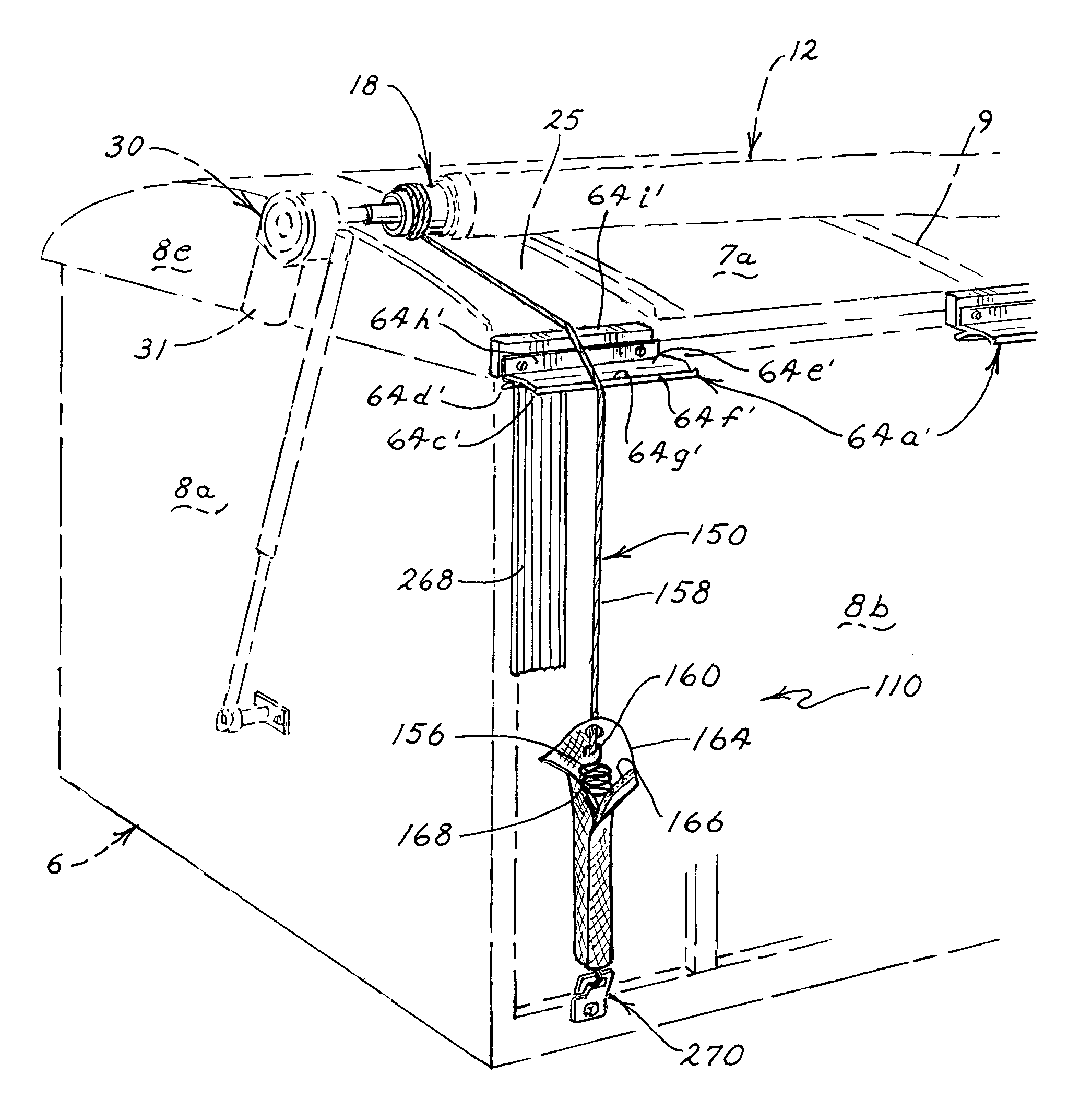
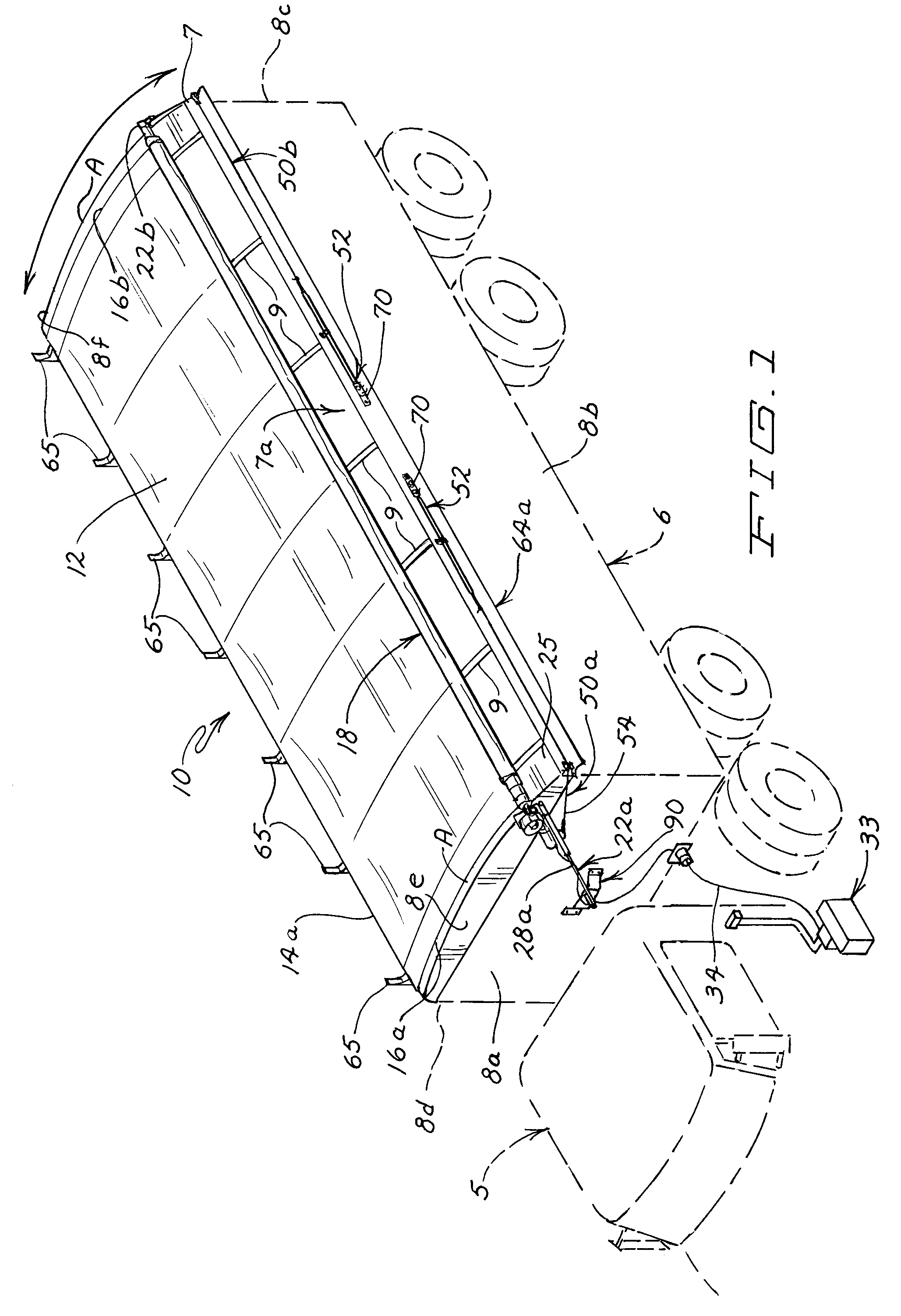
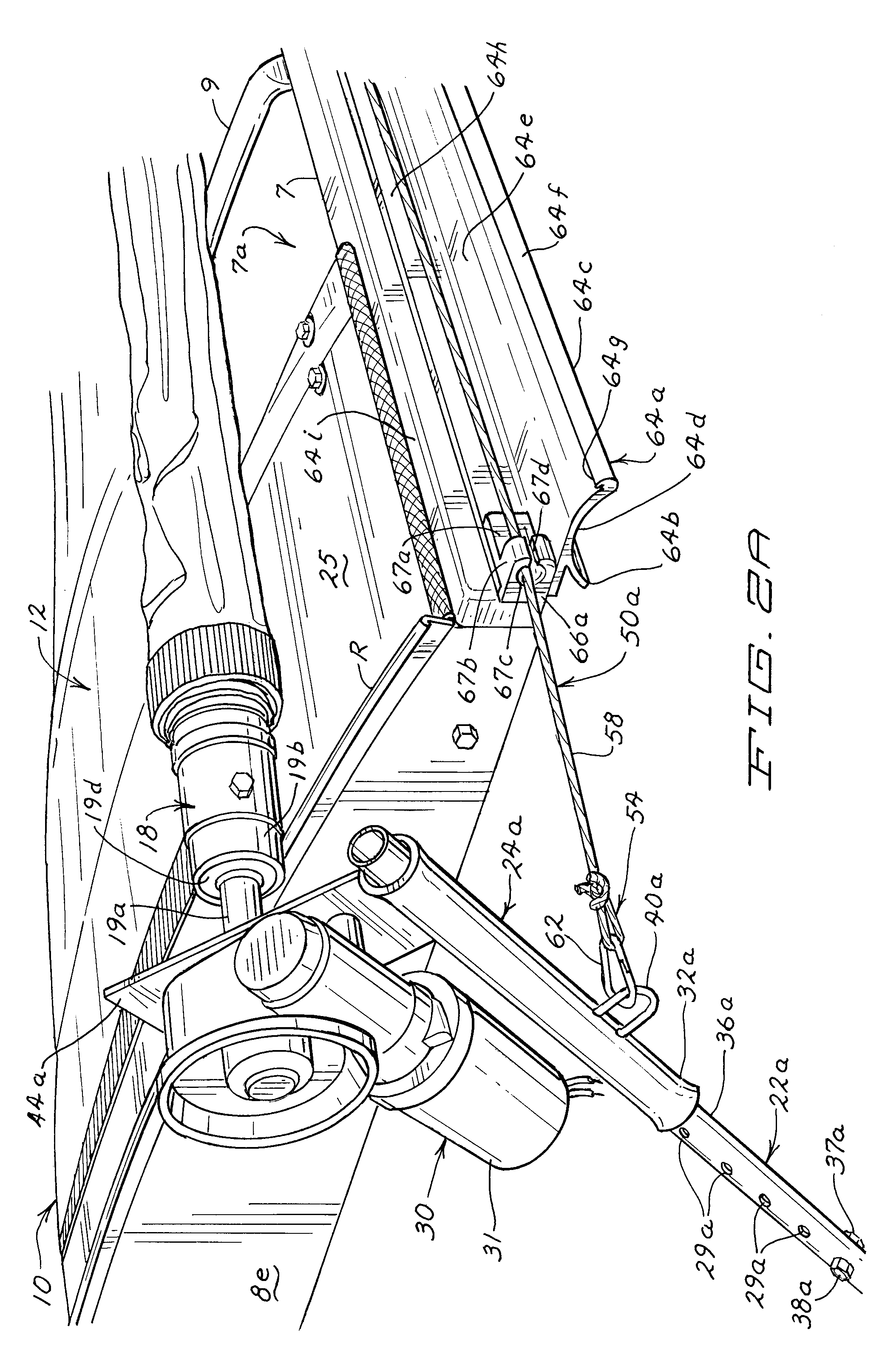
[0057]FIGS. 1-3 illustrate a truck 5 including a truck cargo box or truck box 6 having a bed and four sides 8a-d. In preferred embodiments, the truck box 6 can include one or two end caps 8e and 8f secured over a top 7 of the respective ends 8a, 8c of the truck box 6. Each end cap 8e, 8f includes an end edge, opposing side edges, and a curved outer surface. Note that the top 7 of the truck box 6, which defines a top opening 7a, will be somewhat foreshortened by the use of one or more end caps 8e, 8f. Although in some cases, the roll tarp assemblies of the present invention will not include end caps, because they are sometimes provided by the truck manufacture or have been provided with a previously used roll tarp apparatus, the present invention can include end caps provide for each end of the truck box 6. Similarly, support bows 9, if required and provided, can be provided by the manufacturer of the truck box 6 or alternately provided as a part of an alternate roll-up tarp apparatu...


PUM


Abstract

A roll-up tarp apparatus for a truck box having first and second ends, first and second longitudinal sides and an open top. The apparatus includes a tarp, a roll bar, an arm and a biasing member. The first longitudinal edge of the tarp is interconnected to the first longitudinal side of the truck box and the second longitudinal edge of the tarp is attached to the roll bar member. The roll bar is operatively connected to the truck box and is rotatably movable between the first and second longitudinal sides of the truck box, which enables the tarp to close or open the truck box. At least one biasing member is operatively connected to the roll bar or the arm, with the biasing member able to exert a tensioning force in the direction of the second longitudinal side of the truck box so that the tarp is under tension.

Description

[0001]This application claims priority to U.S. Provisional Application Ser. No. 61 / 051,999 entitled “Roll-Up Tarp Apparatus,” filed on May 9, 2008 and U.S. Provisional application Ser. No. 61 / 169,185 entitled “Roll-up Tarp Apparatus,” filed on Apr. 14, 2009, the disclosures of which are herein incorporated by reference.BACKGROUND OF THE DISCLOSURE[0002]1. Field of the Invention[0003]The present invention relates to roll-up tarp apparatuses for an open top truck cargo box or the like. More particularly, the present invention relates to roll-up tarp apparatuses including an elongated roll bar member that is biased with at least one biasing member.[0004]2. Description of the Related Art[0005]Roll-up tarp apparatuses for truck cargo boxes having an open top are widely utilized in the trucking industry. For example, U.S. Pat. No. 4,505,512 (Schmeichel et al.) discloses a roll-up tarp apparatus for an open truck box or trailer. The roll-up tarp apparatus includes a tarp made from a flexib...

Claims


Application Information

Patent Timeline
IPC IPC(8): B60J11/02
CPCB60P7/04B60J7/085
Inventor SCHMEICHEL, CHARLES M.SIGATY, PAUL D.
Owner AGRI COVER
Features
  • Generate Ideas
  • Intellectual Property
  • Life Sciences
  • Materials
  • Tech Scout
  • Unparalleled Data Quality
  • Higher Quality Content
  • 60% Fewer Hallucinations
Learn More