

Vehicle door structure
a technology for vehicle doors and components, applied in the field of vehicle door structures, can solve the problems of increasing neither and so as to increase the complexity of the vehicle door structure and the number of vehicle door components
- Summary
- Abstract
- Description
- Claims
- Application Information
AI Technical Summary
Benefits of technology
Problems solved by technology
Method used
Image

Examples
first embodiment
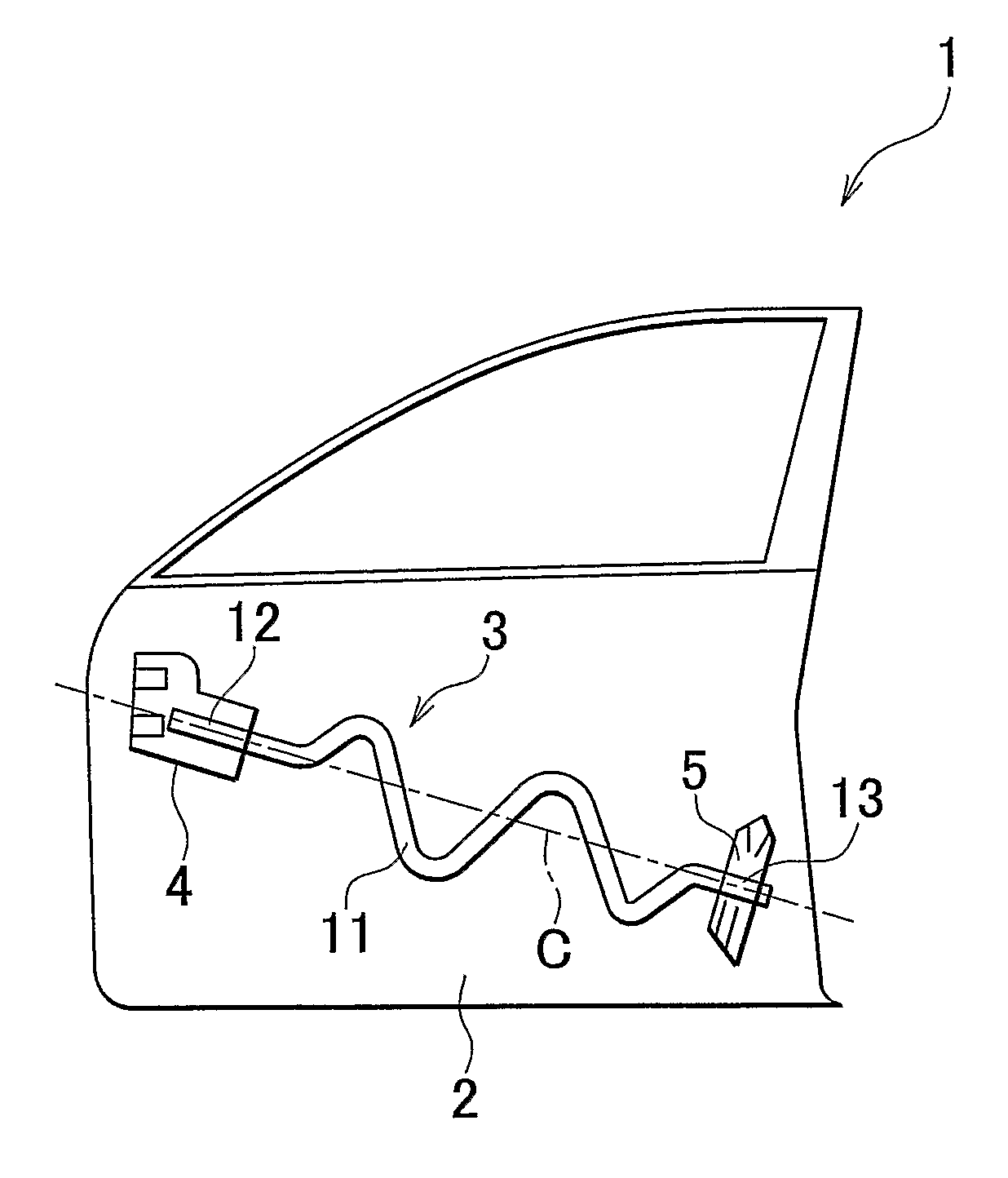
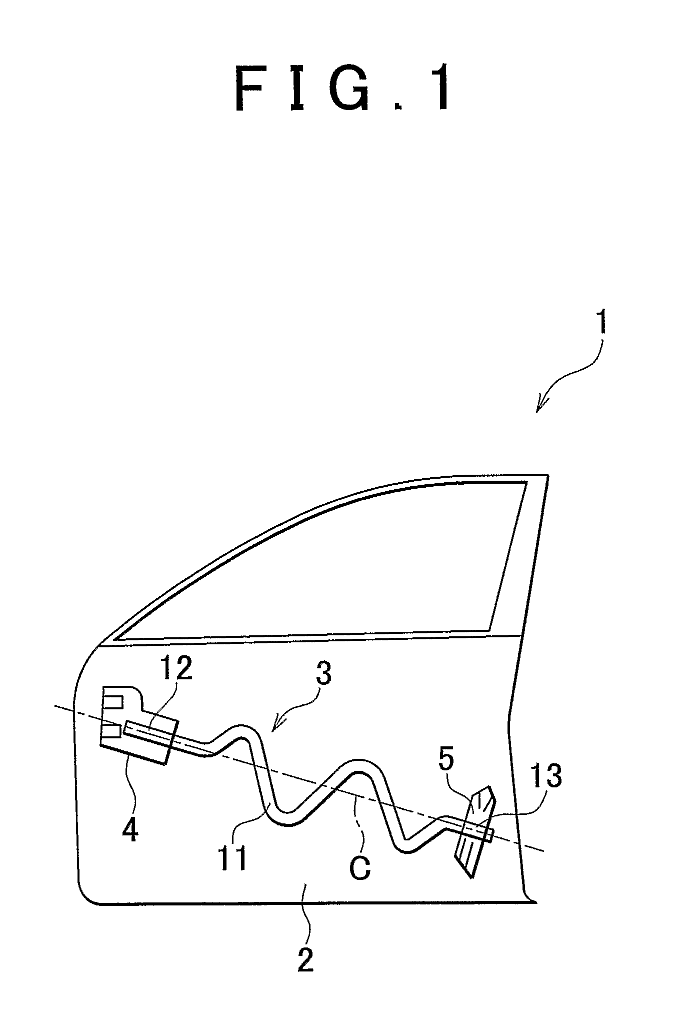
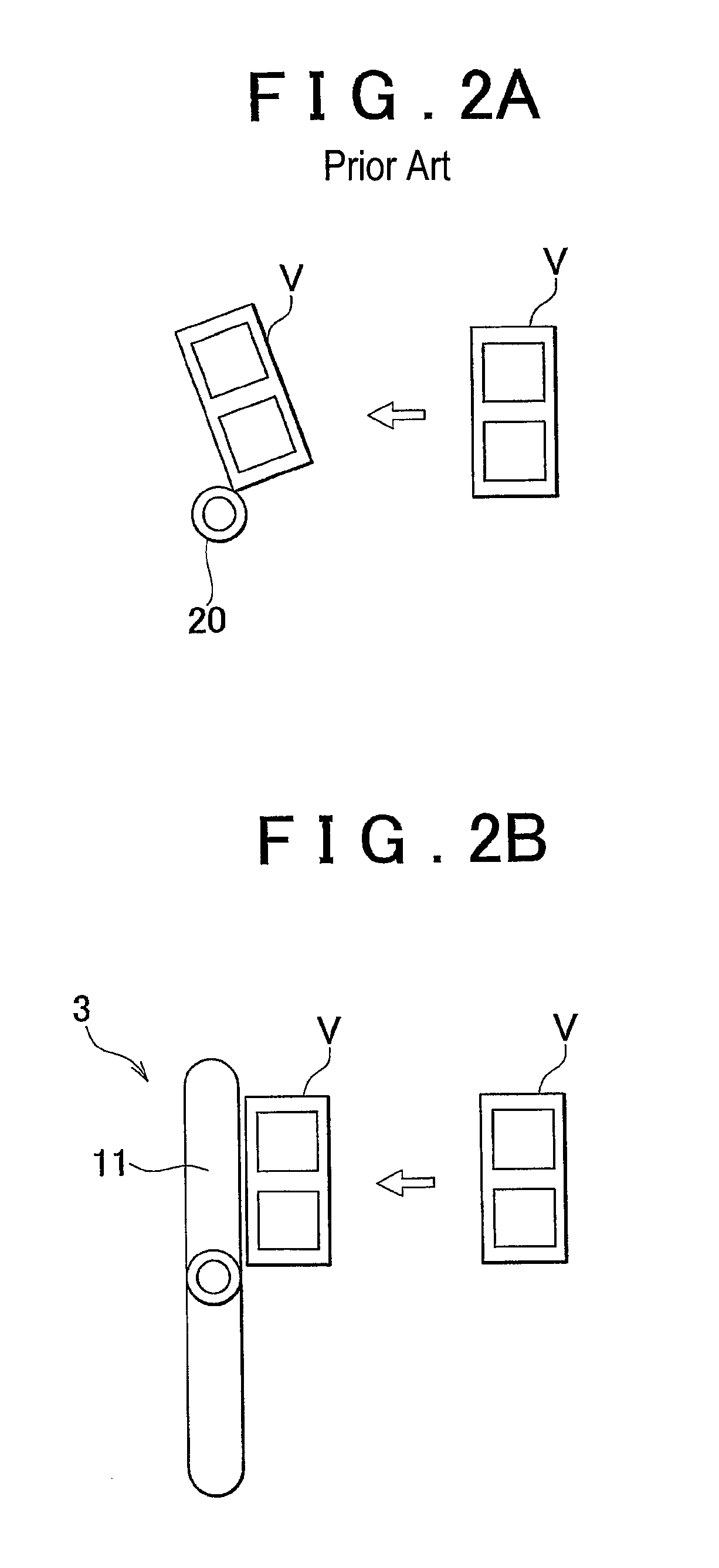
[0025]On the other hand, the impact beam 3 has the wavy portion 11, and the impact beam 3 protects a wider area in the vehicle door 1 in the height direction of the vehicle door 1. Therefore, not only when the other vehicle V collides with the vehicle door 1 at a position near the center axis of the wavy portion 11, but also when the other vehicle V collides with the vehicle door 1 at a position higher than the center axis of the wavy portion 11 as shown in FIG. 2B, a reaction force by which the other vehicle V is pushed back is increased. Accordingly, the protective area in the vehicle door 1, which is protected by the impact beam 3, is widened in the height direction of the vehicle door 1.
[0026]The protective area in the vehicle door 1 may also be widened in the height direction of the vehicle door 1 by, for example, providing a plurality of pipe members in the vehicle door 1. On the other hand, the impact beam 3 according to the first embodiment of the invention is formed by ben...
second embodiment
[0028]As shown in FIG. 3, a vehicle door 10 is provided with the inner panel 2, and an impact beam 30 is attached to the inner panel 2. The impact beam 30 is formed of a pipe member, and disposed along the longitudinal direction of the vehicle (i.e. the width direction of the vehicle door). The impact beam 30 is formed by processing a straight pipe member in such a manner that a wavy portion 31 is formed therein. The wavy portion 31 is formed by bending a portion of the pipe member up and down. The thus formed impact beam 30 is attached to the inner panel 2 in such a manner that the wavy portion 31 undulates in the height direction of the vehicle door 10 in a side view of the vehicle (i.e. in a front view of the vehicle door 10). A front-end portion 32 and a rear-end portion 33, which are contiguous with the wavy portion 31, are formed at respective end portions of the impact beam 30.
[0029]A center axis C of the wavy portion 31 extends along the longitudinal direction of the vehicl...
PUM
 Abstract
Description
Claims
Application Information