
Power management efficiency using DC-DC and linear regulators in conjunction

a technology of linear regulators and power management efficiency, which is applied in the direction of electric variable regulation, process and machine control, instruments, etc., can solve the problems of increasing the power demand of the device, increasing the functionality of the device, and prolonging the typical use duration, so as to reduce the power dissipation at the second stage power regulator, the effect of efficient adjustmen

Active Publication Date: 2015-07-21
NVIDIA CORP
View PDF80 Cites 7 Cited by
  • Summary
  • Abstract
  • Description
  • Claims
  • Application Information

AI Technical Summary

Benefits of technology

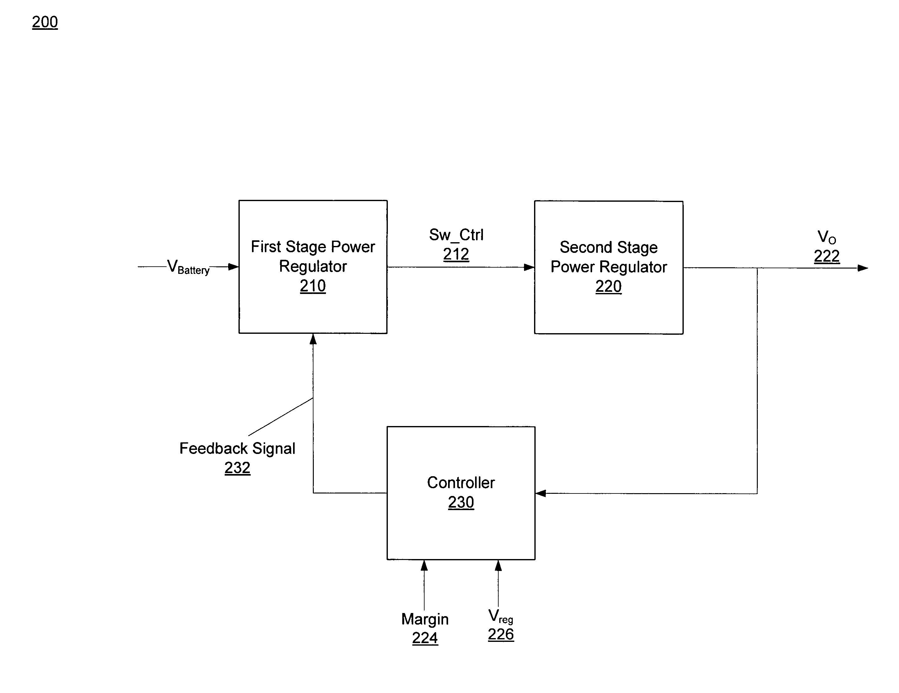
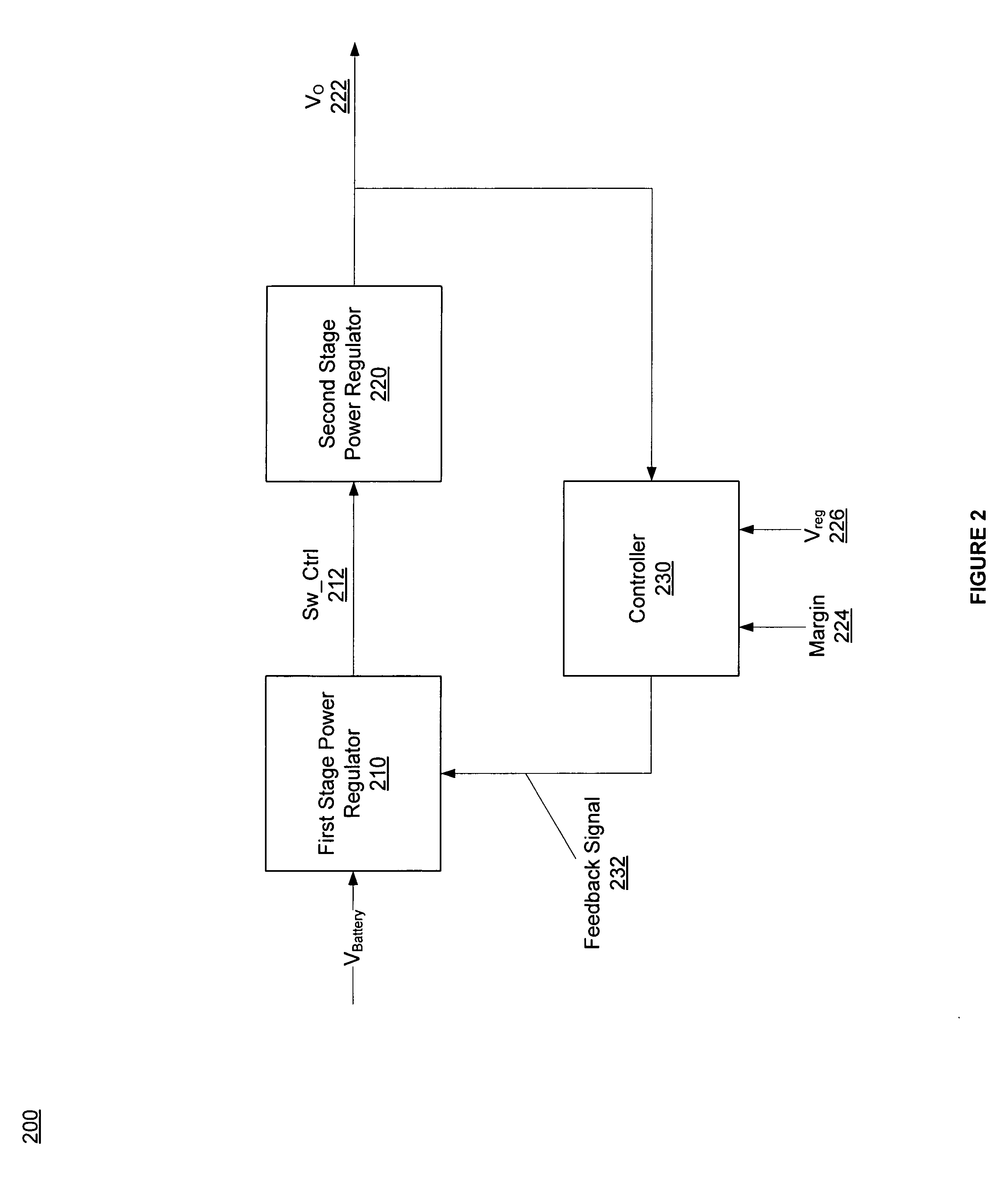
[0009]In one embodiment of the present invention, a two stage power regulator is used along with control circuitry. The first stage power regulator may be a switching regulator that efficiently adjusts an input power signal to a second stage power regulator based on a feedback signal generated by the control circuitry.
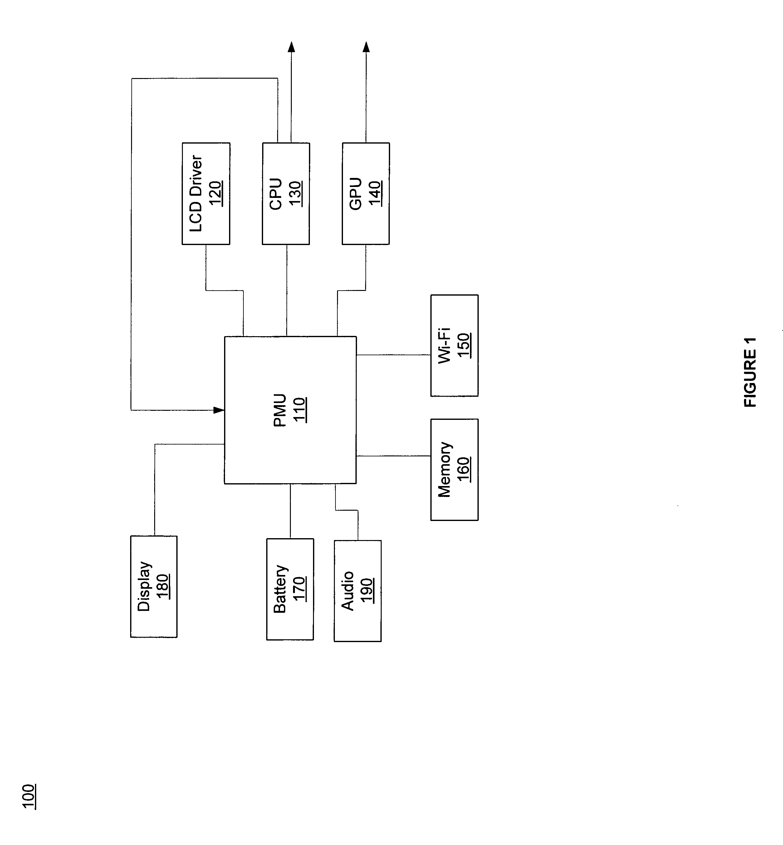
[0011]It is appreciated that the plurality of linear low dropout voltage regulators adjust power by dissipating power and are in general more efficient when the difference between their input and the output voltage is small. It is further appreciated that the input voltage in the first stage power regulator is efficiently adjusted using the switching regulator in the second stage power regulator. Switching regulators regulate input and output power by storing energy electro-magnetically and releasing it as output voltage on demand. Thus, the input voltage to the plurality of linear low dropout voltage regulators is adjusted to be relatively close to their desired output. As a result, power dissipation at the second stage power regulator is reduced. It is further appreciated that the number of linear low dropout voltage regulators is equal to or greater than the number of switching regulators which in one example is only one. Accordingly, the efficiency of the power management unit is improved without substantially increasing the number of external components, system complexity or cost.
[0012]The control circuitry is coupled to the plurality of linear low dropout voltage regulators and receives a plurality of signals from the plurality of linear low dropout voltage regulators. According to one embodiment, the received signals represent the dissipated power by each linear low dropout voltage regulator. The feedback signal is generated in response to the received signals from the plurality of linear low dropout voltage regulators and based on the desired output voltage as well as the adjusted input voltage from the switching regulator. Thus, the generated feedback signal is sent to the switching regulator that in response to the received feedback signal adjusts the input voltage to reduce power dissipation in the second stage, thereby improving the efficiency of the power management unit.

Problems solved by technology

This extends the typical use duration and increases the power demand of the device between recharge cycles.
Unfortunately, increase in the device functionality increases the power demand, thereby increasing the frequency by which the device needs to be recharged by the user.
Unfortunately functionalities places a drain on battery power.
Unfortunately, linear regulators become very inefficient when the difference between their input and output voltage increases because linear regulators regulate the input and output voltage by internally dissipating power.
As a result, the greater the difference between the input and output voltage, the greater the power dissipation becomes, thus the greater the inefficiency becomes.
Unfortunately, switching regulators are in general larger, more complex and more expensive to implement in comparison to linear regulators.

Method used


Image

  • Power management efficiency using DC-DC and linear regulators in conjunction
  • Power management efficiency using DC-DC and linear regulators in conjunction
  • Power management efficiency using DC-DC and linear regulators in conjunction

Examples


Embodiment Construction

[0024]Reference will now be made in detail to embodiments of the present invention, examples of which are illustrated in the accompanying drawings. While the invention will be described in conjunction with these embodiments, it will be understood that they are not intended to limit the invention to these embodiments. On the contrary, the invention is intended to cover alternatives, modifications and equivalents, which may be included within the spirit and scope of the invention as defined by the appended claims. Furthermore, in the following detailed description of the present invention, numerous specific details are set forth in order to provide a thorough understanding of the present invention. However, it will be evident to one of ordinary skill in the art that the present invention may be practiced without these specific details. In other instances, well known methods, procedures, components, and circuits have not been described in detail as not to unnecessarily obscure aspects ...


PUM


Abstract

A power management unit for improving power efficiency of an electronic device. The power management unit includes a first and a second stage power regulator and a control circuitry. The first stage power regulator includes a switching regulator to efficiently adjust an input voltage based on a feedback signal. The adjusted input voltage provides the second stage power regulator that includes low dropout voltage regulators with an input voltage close to its output. Thus, power dissipation in the second stage is reduced by reducing the voltage differential between the input and desired output voltages. The second stage turns on / off power to units of the electronic device. The control circuitry generates the feedback signal based on dropout voltages of the low dropout voltages, the desired output voltage and the adjusted input voltage. The largest dropout voltage is selected and adds it to the desired output voltage to generate the feedback signal.

Description

TECHNICAL FIELD[0001]The embodiments of the present invention relate to the field of power management in electronic devices. More particularly, embodiments of the present invention relate to a method and system for improving the efficiency of a power management unit in an electronic device using DC-DC and linear regulators.BACKGROUND ART[0002]Use of various electronic devices has increased substantially in recent years. For example, use of laptops, mobile telephones, Blackberrys, pagers, IPods, etc. have become common in public places such as coffee shops, restaurants, college campuses, businesses, etc.[0003]Users demand their electronic devices to be integrated such that one electronic device provides various functionalities. For example, most mobile devices (e.g., iPhone, Blackberry, Treo, etc.) can now be operated as a computer, a music player, a game console, a telephone, etc. This extends the typical use duration and increases the power demand of the device between recharge cyc...

Claims


Application Information

Patent Timeline
Patent Type & Authority Patents(United States)
IPC IPC(8): G05F1/00H02J1/08H02M3/28H02M1/00
CPCH02J1/08H02M3/28H02M2001/008H02M2001/0045H02M1/0045H02M1/008
Inventor HENDIN, NEILNAJAM, ZAHID
Owner NVIDIA CORP
Learn More