Vehicle seat

a technology for vehicles and seats, applied in the field of vehicles seats, can solve the problems of narrowing reducing hence the load supported by the plate, so as to reduce the thickness of a specific portion of the adjusting part, narrow the permissible range of plate strength, and reduce the rigidity of the plate

Inactive Publication Date: 2012-07-24
TS TECH CO LTD
View PDF13 Cites 94 Cited by
  • Summary
  • Abstract
  • Description
  • Claims
  • Application Information

AI Technical Summary

Benefits of technology

[0008]The configuration described in the JP No. 2006-21716 of the known examples supports a seated passenger satisfactorily but cannot adjust the elastic force according to the body type of a seated passenger. The configuration described in the JP No. 11-206506 of the known examples decreases cushioning by the rigid body that forms all the four sides of the internal structure. Specifically, since the internal structure in the form of the quadrangular frame is disposed in the quadrangular seat back frame, cushioning in areas other than those providing central lumbar support decreases.
[0009]The configuration described in JP No. 2006-111066 of the known examples has the adjusting part in an area of the plate. In order to bend this adjusting part, the thickness of a specific portion of the adjusting part is decreased. This narrows the permissible range of plate strength. That is, providing the adjusting part on an area of the plate decreases the rigidity of the plate and hence the load supported by the plate. Decreasing the thickness of a specific portion of the adjusting part also decreases the rigidity of the plate and hence the load supported by the plate.
[0010]It is accordingly an object of the present invention to provide a vehicle seat that excels in flexibility according to the body type of a seated passenger.

Problems solved by technology

This narrows the permissible range of plate strength.
That is, providing the adjusting part on an area of the plate decreases the rigidity of the plate and hence the load supported by the plate.
Decreasing the thickness of a specific portion of the adjusting part also decreases the rigidity of the plate and hence the load supported by the plate.

Method used


Image

  • Vehicle seat
  • Vehicle seat
  • Vehicle seat

Examples


Embodiment Construction

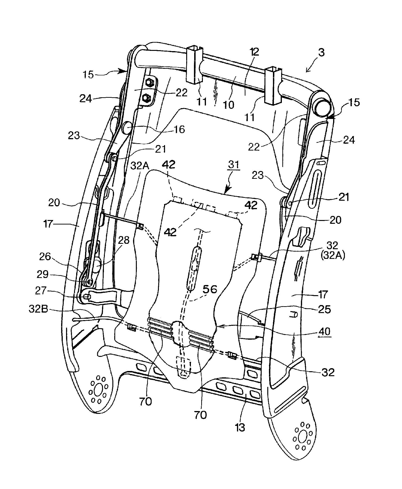
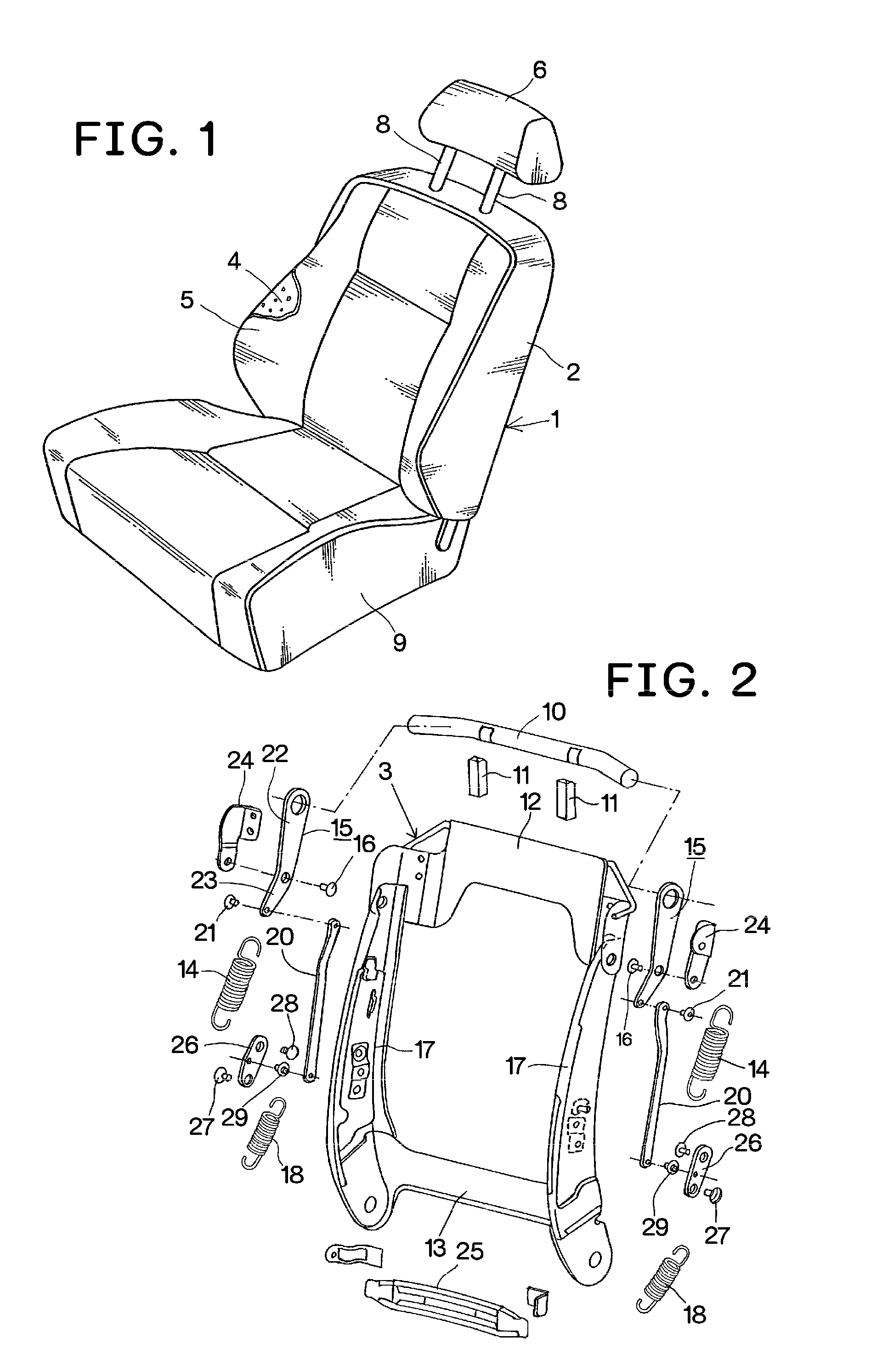
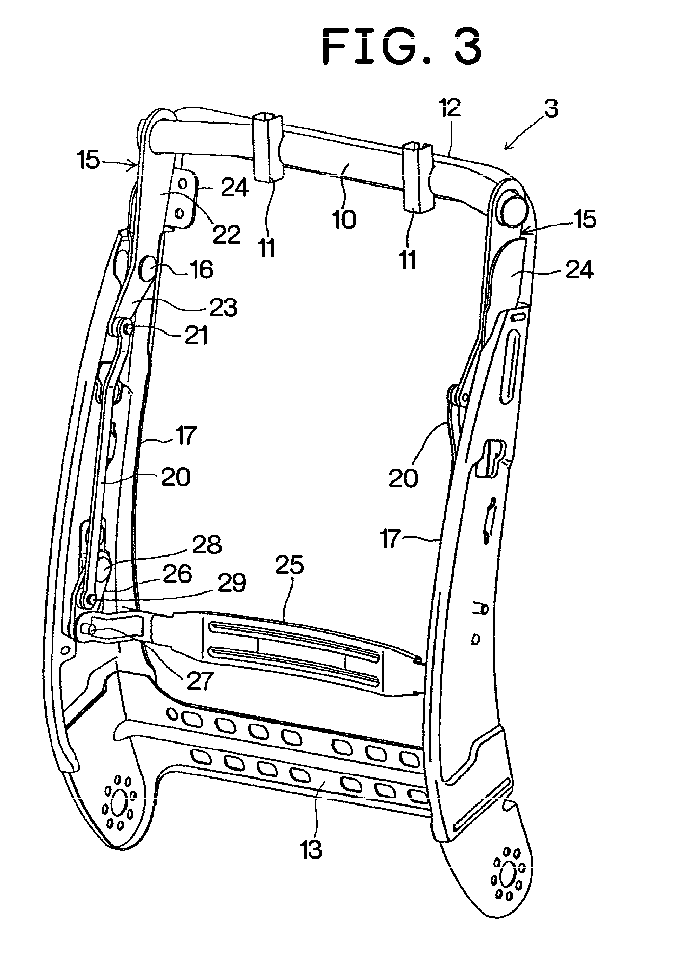
[0025]Embodiments according to the present invention will hereinafter be described with reference to the accompanying drawings. A vehicle seat 1 according to the present invention includes a seat back 2, a seat bottom 9, and a headrest 6 disposed on the top of the seat back 2. A seat back frame 3 for the seat back 2 is quadrangular and has a pair of side frames 17, an upper frame 12, and a lower frame 13. The vehicle seat 1 has a cushion 4 covered with a leather member 5.

[0026]Disposed near the upper frame 12 is a headrest support 10 extending sideways and movable relative to the seat back frame 3. Fixed in the support 10 are vertical engaging parts 11, into which the lower parts of the pillars 8 of the headrest 6 are inserted. The pillars 8 are supported so that their heights may be freely adjusted by the vertical engaging parts 11.

[0027]A bracket 24 is disposed on the upper part of each of the side frames 17 or at each end of the upper frame 12. An upper link or bell crank 15 is a...


PUM


Abstract

A vehicle seat comprises a synthetic resin cushion plate (31) attached to a back frame (3) by way of seat springs (32) so as to be movable forward or backward, a single elastic auxiliary plate (40) attached to the cushion plate (31) so as to be movable forward or backward relative to the cushion plate (31), a specific section of the auxiliary plate (40) formed as a push-out section (70) protruding forward when a distance between an upper edge and a lower edge of the auxiliary plate (40) is shortened by moving the lower edge upward. Elasticity of the auxiliary plate (40) supporting the body of the seated passenger is adjusted by moving the auxiliary plate (40) near the push-out section (70) forward or backward. The push-out section (70) has a corrugated part (71) formed from a sideways projection that projects forward or / and backward as viewed from a side.

Description

TECHNICAL FIELD[0001]The present invention relates to vehicle seats and more particularly relates to vehicle seats that have a mechanism for adjusting the cushion pressure.BACKGROUND ART[0002]A known conventional configuration (e.g., patent document 1) of a vehicle seat is such that a single synthetic resin plate capable of supporting the back of a seated passenger is attached to a seat back frame for a seat back via wire springs so as to freely move forward or backward relative to the seat back frame.[0003]Another known conventional configuration (e.g., patent document 2) of a vehicle seat is such that an internal structure in the form of a quadrangular frame is fixed to a seat back frame, sideways elastic bending parts are attached to the left and right sides of the internal structure, a spring plate is disposed between the elastic bending parts, and lumbar supports are disposed on the upper and lower sides of the spring plate via a vertical elastic bending part.[0004]Another know...

Claims


Application Information

Patent Timeline
Patent Type & Authority Patents(United States)
IPC IPC(8): B60N2/66
CPCB60N2/4885B60N2/66B60N2/6671B60N2/888B60N2/667
Inventor MIZOI, KENSUKE
Owner TS TECH CO LTD
Why Eureka
Try Eureka