Improved self-tapping dental implant

a dental implant and self-tapping technology, applied in dental implants, dental surgery, medical science, etc., can solve the problems of time-consuming and delicate use of a tap, less easy compression of the latter by the bone density, and a much higher screwing torque for dental implants to penetra

Pending Publication Date: 2022-08-11
ANTHOGYR
View PDF0 Cites 0 Cited by
  • Summary
  • Abstract
  • Description
  • Claims
  • Application Information

AI Technical Summary

Problems solved by technology

However, when a dental implant of this kind is inserted into a bone of greater density (conventionally of density D1 or D2 according to the Misch classification), the density of the bone makes the latter less easily compressible, such that the penetration of the dental implant requires a much higher screwing torque, sometimes one that is too high to be supported without damage by the dental implant (in particular at the level of its connections allowing it t

Method used


Image

  • Improved self-tapping dental implant
  • Improved self-tapping dental implant
  • Improved self-tapping dental implant

Examples


Embodiment Construction

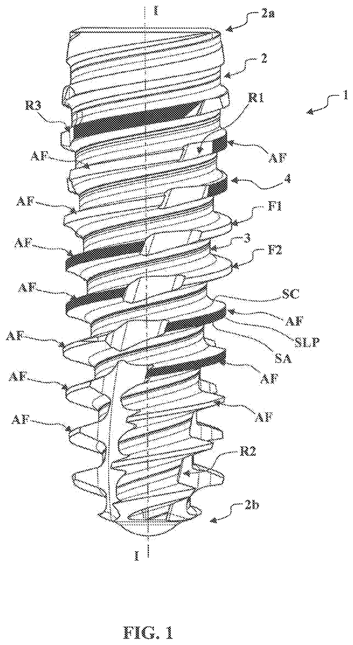
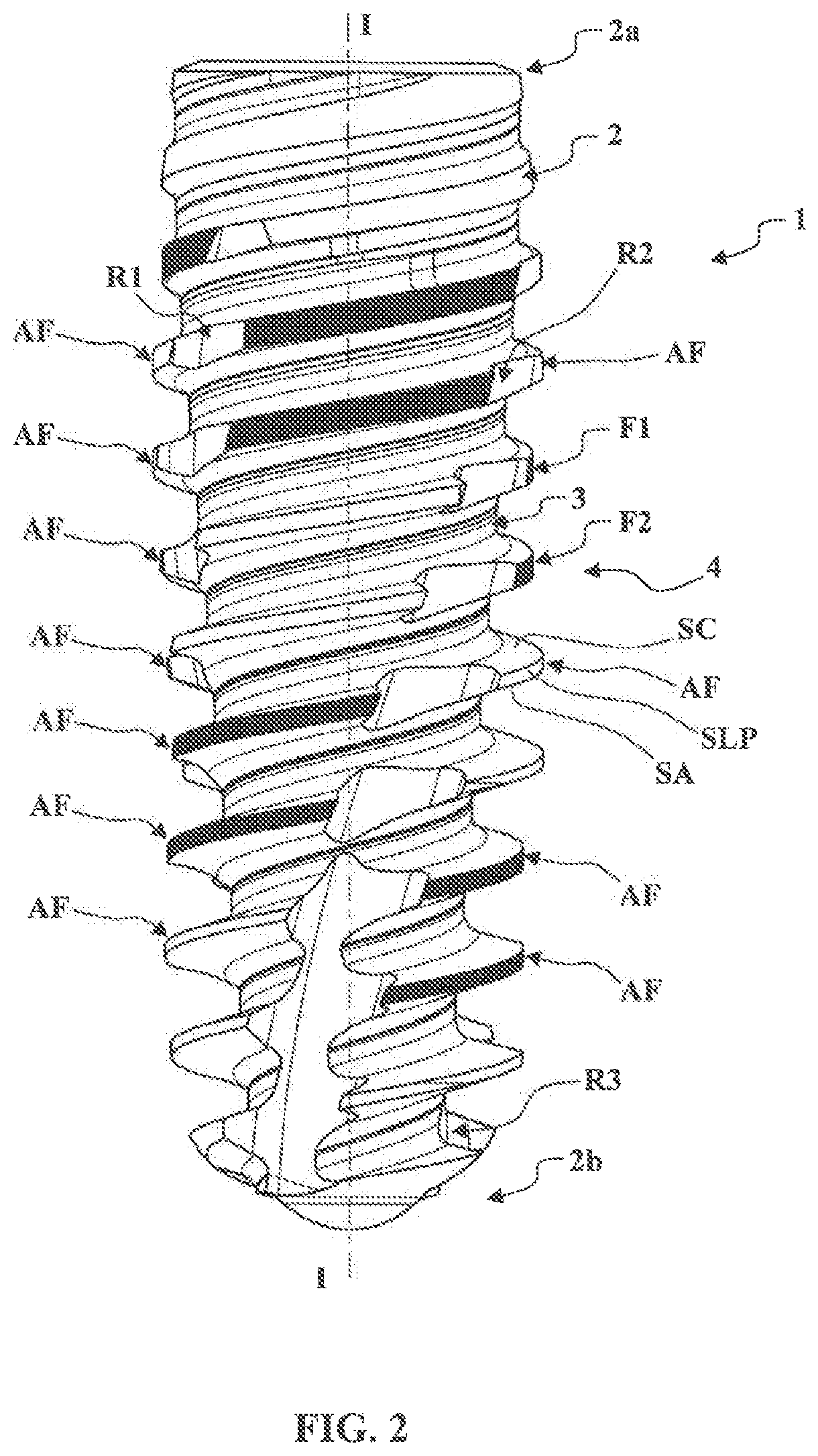
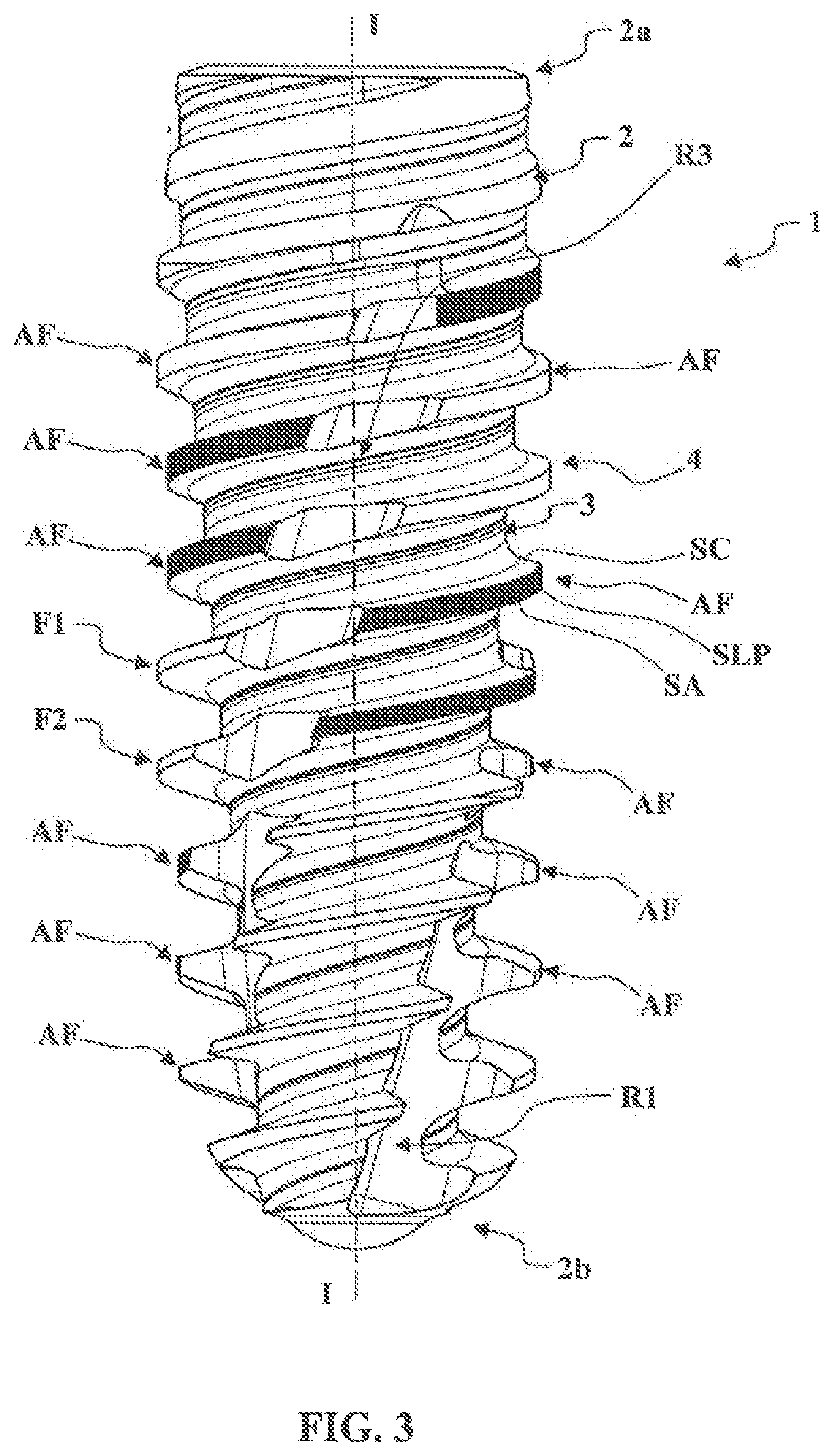
[0042]FIGS. 1 to 7 illustrate a particular embodiment of a dental implant 1 according to the invention.

[0043]As is illustrated in FIGS. 1 to 5, the dental implant 1 comprises an implant body 2 extending along a longitudinal axis I-I between a coronal end 2a and an apical end 2b. The implant body 2 has a core 3, along which there extends a helical threading 4 with at least one thread. In this case, the threading 4 here comprises two threads F1 and F2.

[0044]In FIG. 5, broken lines have been used, to illustrate the outer envelope 5 of the implant body 2 or envelope of the peripheral lateral surfaces of the threads F1 and F2. The envelope of the core 3 has also been illustrated by means of broken lines. It can thus be seen that the implant body 2 comprises five segments T1 to T5 from its coronal end 2a to its apical end 2b.

[0045]In the segment T1, the core 3 is substantially cylindrical, while the threading 4 is conical with a taper oriented toward the coronal end 2a. The height of the...


PUM


Abstract

A dental implant includes an implant body extending along a longitudinal axis between a crown end and an apical end, the implant body having a core along which a helical thread extends with at least one thread, the core being tapered towards the apical end on at least one section of the length of the dental implant. At least two tapping grooves are arranged in the thread. The grooves interrupt the thread, so that the thread includes a series of consecutive thread arcs. Each thread arc has an apical surface oriented towards the apical end of the dental implant, and a crown surface oriented towards the crown end of the dental implant. A peripheral lateral surface connects the apical surface and the crown surface of the thread arc. In at least one section of the dental implant in which the core is tapered, at least one thread arc has a radial offset.

Description

TECHNICAL FIELD OF THE INVENTION[0001]The present invention relates to the field of dental implantology, more particularly to a self-tapping dental implant.[0002]When placing an implant in the maxillary or mandibular bone of a patient, it is important to obtain the best possible post-implantation stability (called primary stability) in order to be able to load said implant as quickly as possible, or even immediately, that is to say before the bone has had time to colonize the endosseous surface of the implant.[0003]The primary stability of an implant depends in particular on the density of the bone in which it is implanted.[0004]When the bone is of low density (conventionally of density D3 or D4 according to the Misch classification), a cylindrical hole is made in the maxillary or mandibular bone using a drill, in which hole there is then inserted the end osseous part of a dental implant having a volume greater than the volume of the hole made in the bone. It is possible, for exampl...

Claims


Application Information

Patent Timeline
IPC IPC(8): A61C8/00
CPCA61C8/0025A61C8/0024A61C8/0022
Inventor RICHARD, HERVÉ
Owner ANTHOGYR
Why Eureka
Try Eureka