Tool for chip removing machining having a screw-actuated clamp

a technology of screw-actuated clamps and tools, which is applied in the direction of tool holders, shaping cutters, manufacturing tools, etc., can solve the problems of screw after a certain time, the support of the cutting insert against the bottom surface of the seat becomes unsatisfactory, and the cutting insert completely lacks the support area of the outer end of the slo

Inactive Publication Date: 2002-11-21
SANDVIK INTELLECTUAL PROPERTY AB
View PDF0 Cites 4 Cited by
  • Summary
  • Abstract
  • Description
  • Claims
  • Application Information

AI Technical Summary

Benefits of technology

[0049] Beside the general advantage of enabling clamping of the cutting insert by means of a screw which is accessible from a direction other than the side in which the insert seat is formed, the cutting tool according to the invention has the advantage that the cutting insert receives a satisfactory support along all edge portions, since the bottom surface of the seat completely surrounds the finger 18. In this way, the risk of breakage of the cutting insert and / or the creation of deformations in the shaft or the insert holder is reduced. Furthermore, thanks to the top side of the clamping body 16 being supported against a flange 29, which surrounds the hole for the finger of the clamping body, the risk of deflection deformations in the screw and in the clamping body finger are counteracted. Moreover, such deflection deformations are counteracted by the fact that the screw is supported at each of the two opposite ends thereof, viz. in the cylindrical bore 20, as well as in the depression 34 or 39 in the end wall 27.FEASIBLE MODIFICATIONS OF THE INVENTION[0050] The invention is not solely restricted to the embodiments described above and illustrated in the drawings. Thus, it is possible to provide the clamping mechanism in shafts or insert holders other than those having a quadrangular cross-sectional shape. Thus, the shaft may have a circular cross-sectional shape or a polygonal cross-sectional shape other than quadrangular. It is essential according to the invention that the screw for the clamping body is accessible from a direction other than the first side 4 in which the seat for the cutting insert is located. In the embodiments according to FIGS. 10-13, the head of the tightening screw may have a shape other than conical. For instance, the screw head may be flat or cylindrical and arranged to be pressed against a plane, ring-shaped abutment surface instead of against a conical abutment surface. In conclusion, it should be pointed out that the screw for the clamping body may be formed with means other than a polygonal socket for spanners. For instance, the screw may be formed with a groove for a screwdriver. The concept "spanner socket" should thus be interpreted in a broad sense to includes such other means.

Problems solved by technology

One disadvantage is that the cavity for the clamping body is open in the side of the shaft opposite the screw bore, whereby the clamping body is inserted from that opposite side while the finger on the clamping body passes through an open slot formed in the bottom of the cutting seat.
This means that the support of the cutting insert against the bottom surface of the seat becomes unsatisfactory.
Furthermore, the cutting insert completely lacks support in the area of the outer end of the slot.
Another disadvantage is that the screw after a certain time of usage, risks being deformed by bending in connection with the repetitive clamping operations, since only one end of the screw is actually supported, i.e., the screw is supported in cantilever fashion.
An additional disadvantage of the known construction is that the same includes no less than four threads, viz. two male threads on the screw and two female threads (in the bore in the shaft and the hole in the clamping body, respectively).
To produce threads is a generally cost-demanding machining operation which entails that the cutting tool in its entirety becomes expensive to manufacture.

Method used


Image

  • Tool for chip removing machining having a screw-actuated clamp
  • Tool for chip removing machining having a screw-actuated clamp
  • Tool for chip removing machining having a screw-actuated clamp

Examples


Embodiment Construction

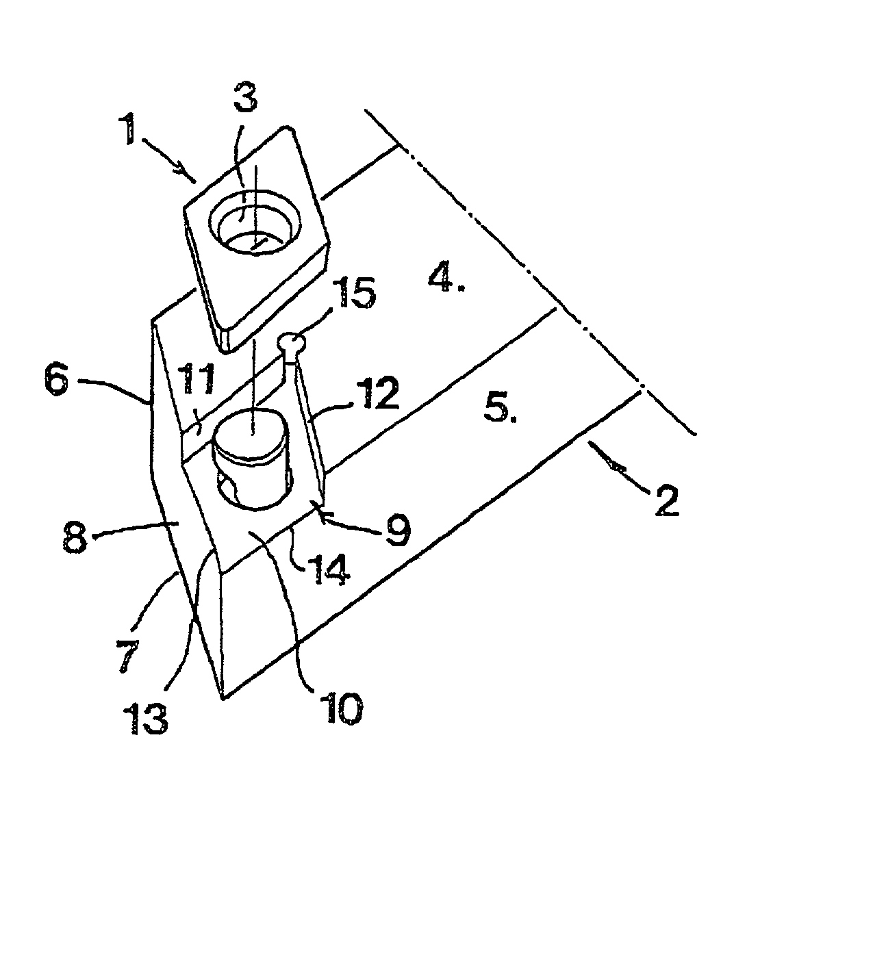
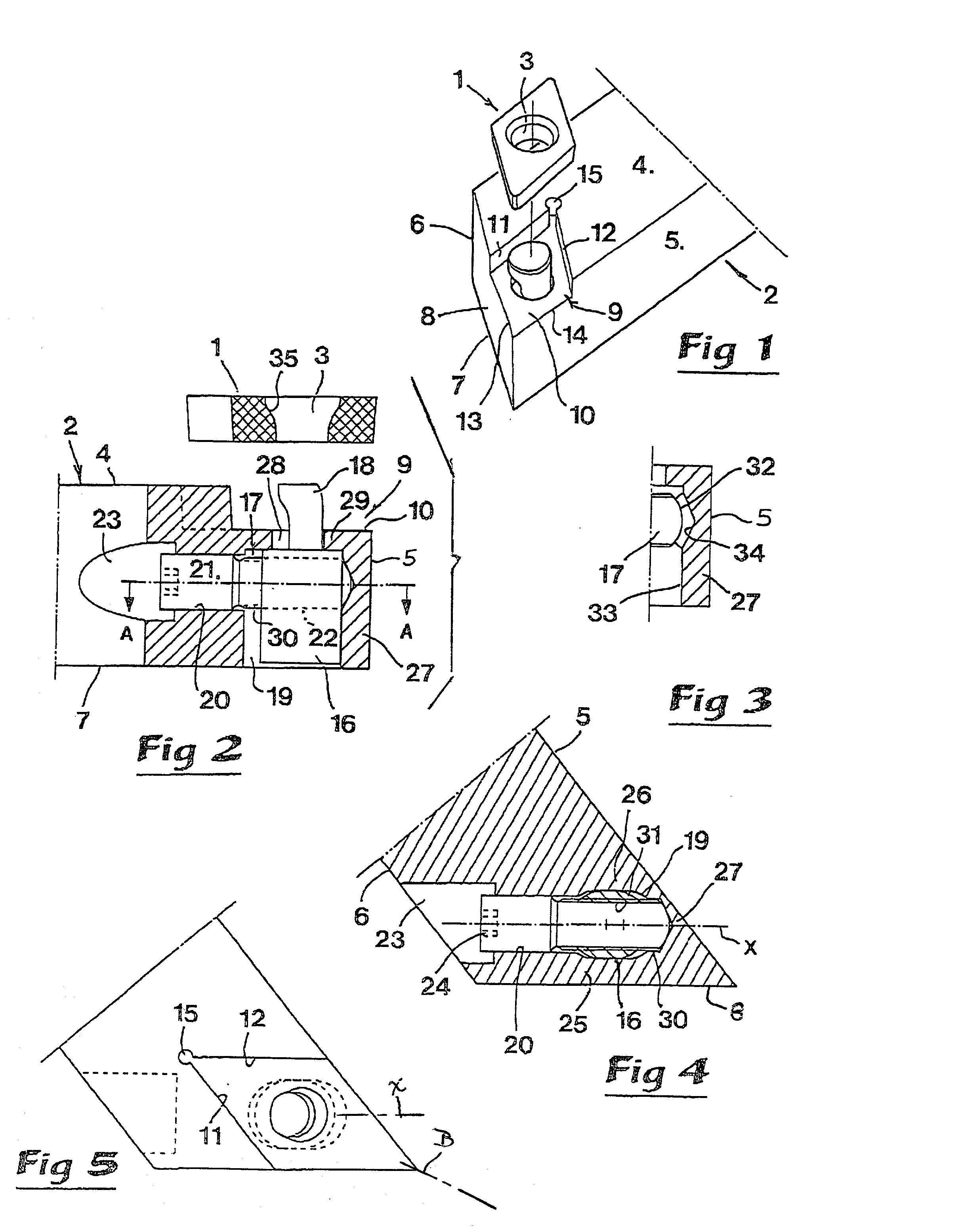
[0023] The cutting tool illustrated in FIG. 1 is intended for turning and is composed of a cutting insert 1 and a holder 2. In the example, the cutting insert 1 consists of an indexable cutting insert having a rhombic basic shape. In the cutting insert, there is a central hole 3. The insert holder 2 consists of a long narrow shaft, which in the example is shown having a quadrangular cross-sectional shape. Generally, the shaft is thus defined by four sides defining respective plane surfaces 4-7. A first of those surfaces 4 will, for the sake of simplicity, henceforth be denominated as a top surface, while the surfaces 5, 6 will be denominated side surfaces and the surface 7 a bottom surface. In this connection, it should, however, be emphasised that the tool in practical use may be oriented in any arbitrary way in space. A front-end surface 8 extends at an acute angle to the side surface 5 (in the example, the nose angle is 50.degree.). Each of the surfaces 5, 6 interconnects the sur...


PUM

PropertyMeasurementUnit
nose angleaaaaaaaaaa
conical shapeaaaaaaaaaa
spherical shapeaaaaaaaaaa

Abstract

A tool for chip removing machining includes a holder having a top side in which is formed a seat for a cutting insert to be clamped by a clamping mechanism. That clamping mechanism includes a clamping body movable inside a cavity formed in the holder. The body carries a finger which passes through a hole formed in a bottom surface of the seat and engages the cutting insert. A rotatable screw is provided in a bore of the holder and extends into the cavity. The screw is formed with a thick first portion, as well as a thinner second portion having a male thread which is in engagement with a female thread formed in a through-hole of the clamping body. The bore in the holder is cylindrical and has a smooth surface, and the thick portion of the screw has a cylindrical smooth envelope surface which is rotatably mounted in the bore. A free end of the screw is supported by an end wall of the holder. The finger is completely surround by the bottom surface of the seat.

Description

[0001] This application claims priority under 35 U.S.C. .sctn..sctn.119 and / or 365 to Patent Application Serial No. 0101565-0 filed in Sweden on May 7, 2001, the entire content of which is hereby incorporated by reference.[0002] This invention relates to a tool intended for chip removing machining, including a holder having a seat formed in a first side for a cutting insert of the type that includes a hole for clamping the same. The clamping is performed by means of a clamping mechanism that comprises a clamping body provided with a finger, which is movable backwards and forwards inside a cavity in the interior of the holder and cooperates with a screw arranged in a bore formed in the holder. The bore ports in a second side of the holder, distanced from said first side, with the purpose of enabling access to the screw from a direction other than from the first side along which the seat is located. The screw is formed with a thick, first portion, as well as a thinner, second portion,...

Claims


Application Information

Patent Timeline
Patent Type & Authority Applications(United States)
IPC IPC(8): B23B27/16
CPCB23B27/1662Y10T407/227Y10T407/2276Y10T407/2272B23B27/16
Inventor SHIRAIWA, AKIO
Owner SANDVIK INTELLECTUAL PROPERTY AB
Why Eureka
Try Eureka