Anti-fouling coatings for combustion system components exposed to slag, ash and/or char

a technology of anti-fouling coatings and combustion system components, which is applied in the direction of chemical coatings, liquid/solution decomposition, mechanical details of gasifiers, etc. it can solve the problems of no physical barrier coatings that are designed, slag, ash, and/or char buildup on internal surfaces, etc., and achieve the effect of preventing slag, ash, and/or char buildup

Active Publication Date: 2012-07-24
PROCTER & GAMBLE CO +1
View PDF12 Cites 17 Cited by
  • Summary
  • Abstract
  • Description
  • Claims
  • Application Information

AI Technical Summary

Benefits of technology

[0007]Disclosed herein are combustions systems, anti-fouling coatings for various components used in combustion systems, and processes for preventing slag, ash, and / or char buildup on components used in combustion systems. In one embodiment, a combustion system comprises a coating of pure or alloyed refractory metal particles in a metal, ceramic or glass matrix disposed on a surface of the system that is prone to slag, ash, and / or char buildup during operation of the combustion system, wherein the coating is effective to prevent any substantial interaction with the slag, ash, and / or char.
[0008]A process for preventing slag, ash, and / or char buildup on a surface, the process comprises alloying, during deposition, a coating of refractory metal particles in a ceramic, glass or metal matrix on a surface that is prone to slag corrosion, slag buildup, ash buildup, and / or char buildup during operation of a combustion system.

Problems solved by technology

One of the problems in current combustion systems such as the IGCC system discussed above or in gas turbines for either aviation or land based (CMOS) is the build up of slag, ash, and / or char on internal surfaces i.e., surface fouling.
There are currently no physical barrier coatings that are designed to prevent ash deposition onto and slag reaction with surfaces in contact therewith at the high combustion temperatures found in gasification plants or potentially other combustion systems.
The push to use ceramics for higher operating temperatures in fossil fuel combustion systems is dramatically limited by the reducing atmosphere present within and the deposition and chemical attack by slag byproducts contained in the combustions gases.

Method used


Image

  • Anti-fouling coatings for combustion system components exposed to slag, ash and/or char
  • Anti-fouling coatings for combustion system components exposed to slag, ash and/or char
  • Anti-fouling coatings for combustion system components exposed to slag, ash and/or char

Examples


example 1

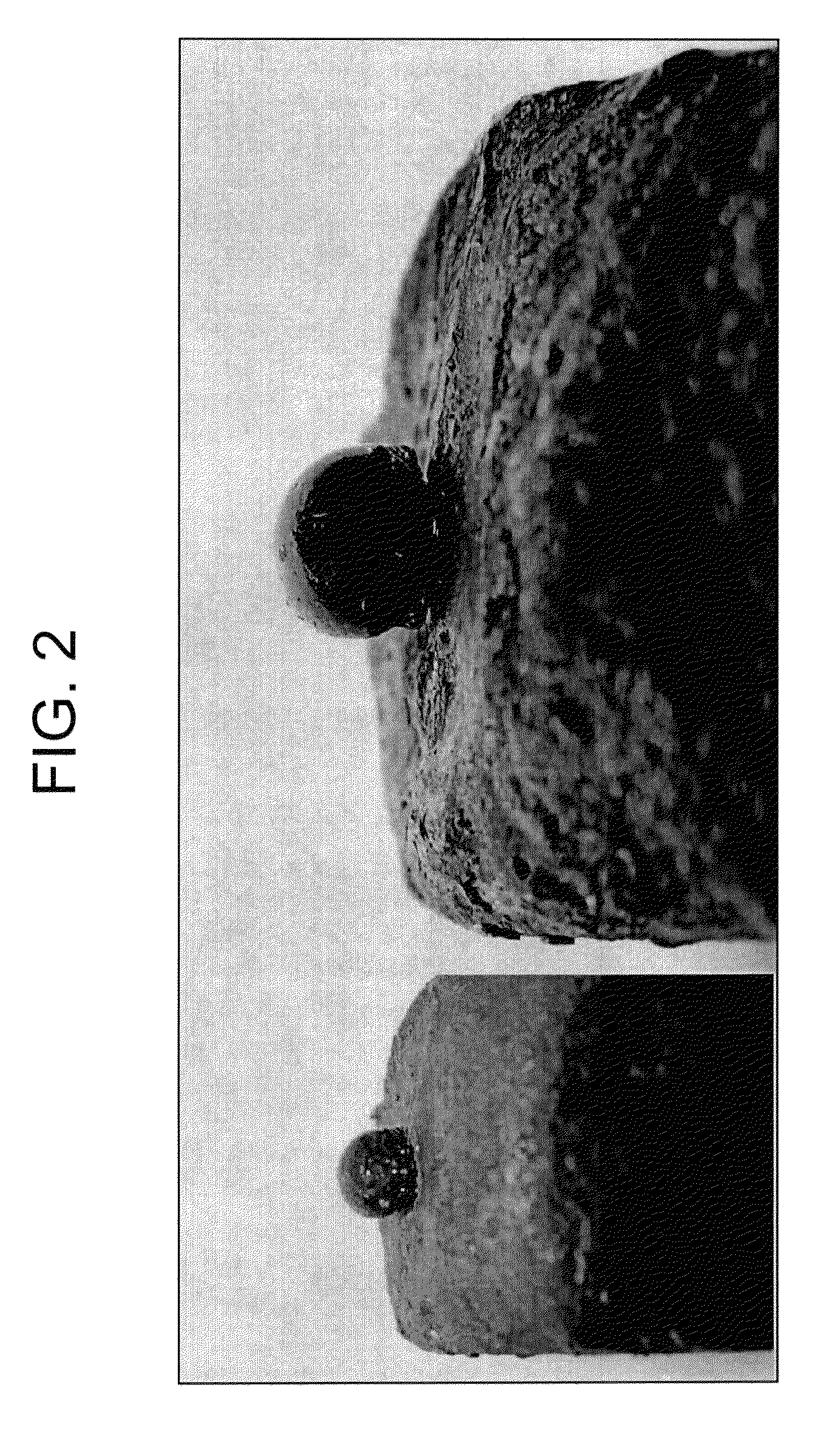
[0032]In this example, an electrospark process was utilized to deposit a coating onto a substrate. A slag piece was positioned onto the coated substrate and subsequently heated to melting using a gas burner. FIG. 2 pictorially illustrates the slag piece “beading” up on an electric arc coating, which exhibited no reaction with the coating. It should be noted that in the absence of the coating, the slag upon melting would wet the surface of the substrate. FIG. 3 pictorially illustrates a sectional view of the refractory metal / silicate coating. As shown, the coating exhibited uniform nano- and microspheres of refractory metal embedded within a silicate matrix. Examination of the silicate matrix illustrated this to be amorphous with some crystalline structures.

example 2

[0033]In this example, an electrospark process was utilized to deposit a coating onto a metal coupon. A slag piece was positioned onto the coated substrate and subsequently heated using a gas burner as in Example 1. FIG. 4 pictorially illustrates a refractory metal / silicate coating that had been deposited onto a metal coupon. Again, the slag appears to have been repelled by the surface and formed a droplet that exhibited no interaction with the coated surface. In this example the substrate could be a machined component onto which the coating has been applied.


PUM

PropertyMeasurementUnit
temperatureaaaaaaaaaa
sizeaaaaaaaaaa
pressuresaaaaaaaaaa

Abstract

A coating for use in combustion systems includes a plurality of refractory metal particles in a ceramic, glass or metal matrix disposed on surfaces of the system that are prone to slag, ash, and / or char buildup during operation of the combustion system. The coating is effective to prevent any substantial interaction with the slag, ash, and / or char.

Description

BACKGROUND[0001]The present disclosure generally relates to anti-fouling coatings for use on components employed in combustion systems and exposed to slag, ash, and / or char.[0002]Combustion systems, such as gasifiers and pulverized coal fired plants, are often used to convert carbon based feedstocks to synthetic gas, called “syngas.” Gasification can use a wide range of fuels including coal, petroleum coke, biomass, oil refinery bottoms (waste oil), digester sludge, and virtually anything that contains carbon and can be fed into a gasification chamber. The high temperature (generally at about 1150 to about 1,700° C.) melts the inert material and then flows to the bottom of the gasification vessel where it is cooled into a glass-like non-leachable inert slag. This slag is used primarily as aggregate in road gravel or concrete applications.[0003]In an integrated gasification combined cycle (IGCC) facility, an air separation unit separates air into its component parts and sends the gas...

Claims


Application Information

Patent Timeline
Patent Type & Authority Patents(United States)
IPC IPC(8): B32B9/00
CPCC10J3/506C23C26/00C10J3/74Y10T428/256C10J2200/09C10J2200/152C10J2300/0959C10J2300/0973C10J2300/165C10J2300/1671C10J2300/1675C10J2300/1678C10J2300/1838Y02E20/18Y02E20/16
Inventor MORRA, MARTIN MATHEWAVAGLIANO, AARON JOHNCHEN, WEIFRUTSCHY, KRISTOPHER JOHNHARNED, MONTY L.TALYA, SHASHISHEKARA S.STOREY, JAMES MICHAEL
Owner PROCTER & GAMBLE CO
Why Eureka
Try Eureka