Thermionic emission device

a technology of emission device and thermal emission, which is applied in the manufacture of electric discharge tube/lamp, discharge tube main electrode, and discharge tube system, etc., can solve the problems of unwanted enlargement of focal spot, achieve high quality of focal spot, avoid unwanted widening or defocusing of electron beam, and simple design

Active Publication Date: 2012-07-24
SIEMENS HEALTHCARE GMBH
View PDF15 Cites 8 Cited by
  • Summary
  • Abstract
  • Description
  • Claims
  • Application Information

AI Technical Summary

Benefits of technology

[0009]An object of the invention is to provide an emission device of the aforementioned type in which an optimally high quality of the focal spot is achieved with a structure that has a simple design, and in which an unwanted widening or defocusing of the electron beam is avoided even at high thermal load.
[0016]The terminal lugs of the heating emitter advantageously do not project beyond the heat emission surface in the lateral direction. A minimal space requirement in a lateral regard is achieved when both the heat emission surface and the terminal lugs of the heating emitter do not project laterally beyond the primary emission surface.
[0020]In another embodiment, each emitter—primary emitter and heating emitter—has exactly two terminal lugs, and the two emitters are arranged such that the in total four terminal lugs essentially stand in a row. This means that the two terminal lugs of the heating emitter essentially stand spatially between the terminal lugs of the primary emitter. This arrangement allows an improvement of the focal spot quality in that the heating current and the current through the primary emission surface are directed in opposite directions and with essentially identical amperage. The two magnetic fields generated by the current largely compensate one another in this manner. It is thus avoided that the magnetic field generated by the heating current affects the electron paths in an unwanted manner.
[0021]The emission surfaces of both emitters are advantageously fashioned as circles. An optimal volume utilization in an extremely asymmetrical design is achieved in this way.
[0022]In another embodiment, the primary emission surface is surrounded with segments that preferably respectively have the shape of a circular ring segment, wherein every segment is connected with the (advantageously circular) primary emission surface via (advantageously) one or more narrow webs. The segments provided to decrease temperature at the edges of the emission surface should thereby have no direct connection with one another. It has proven to be advantageous to select the webs such that essentially no current flows from the primary emission surface into the segments, and that furthermore essentially no heat transport occurs from the primary emission surface via the webs into the segments. As a result, the segments do not emit electrons, which would lead to an enlargement of the focal spot. The equipotential areas of the electrical potential at the edge of the emission surface are deskewed by the webs, so bending of the electron paths of the electrons emitted from the edge area is prevented. The ring made of segments also shields electrons that are thermionically released from the side of the emitter facing away from the anode.

Problems solved by technology

Moreover, in such a conventional design a certain portion of thermally excited electrons can also escape from the terminal lugs in the operating state and be accelerated in the direction of the anode, so an unwanted enlargement of the focal spot results.
In such configurations it is disadvantageous when the elements that serve to structurally fix the emitters and for current feed laterally project beyond the primary emission surface.

Method used


Image

  • Thermionic emission device
  • Thermionic emission device
  • Thermionic emission device

Examples


first embodiment

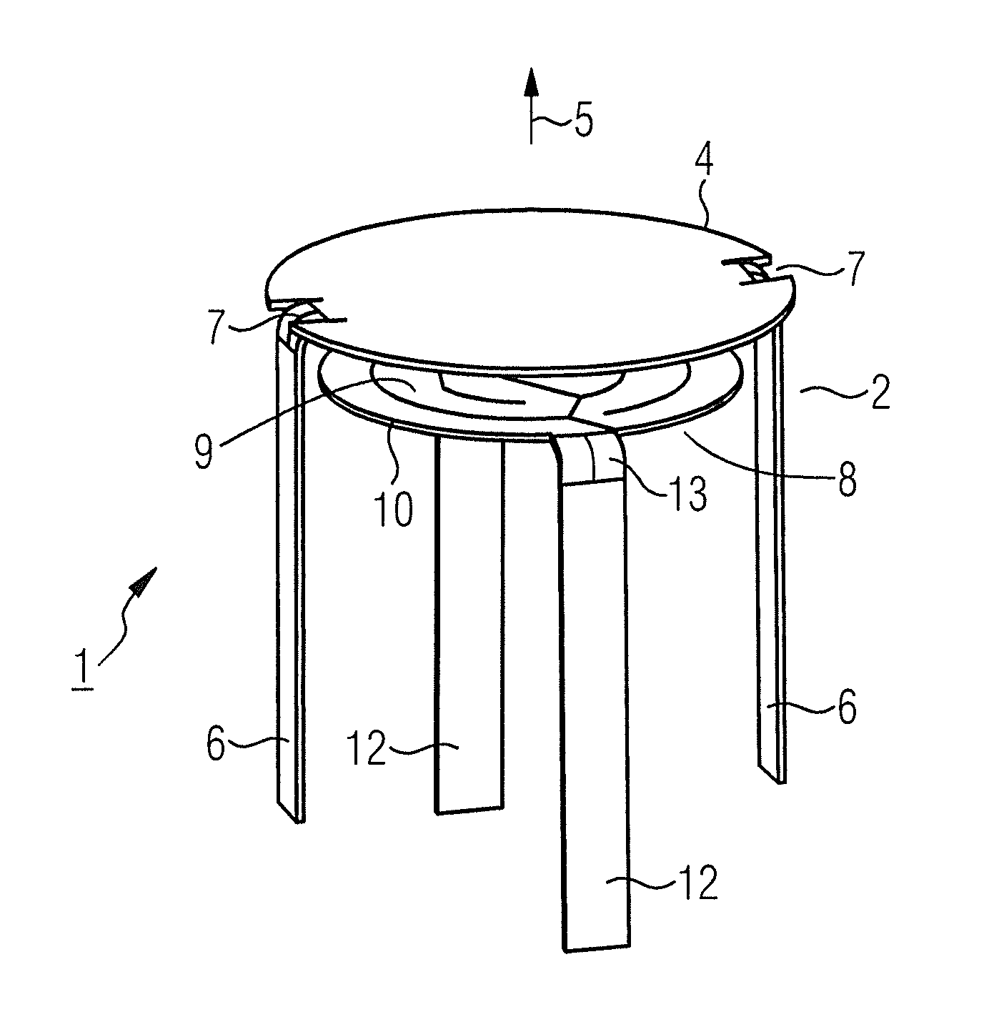
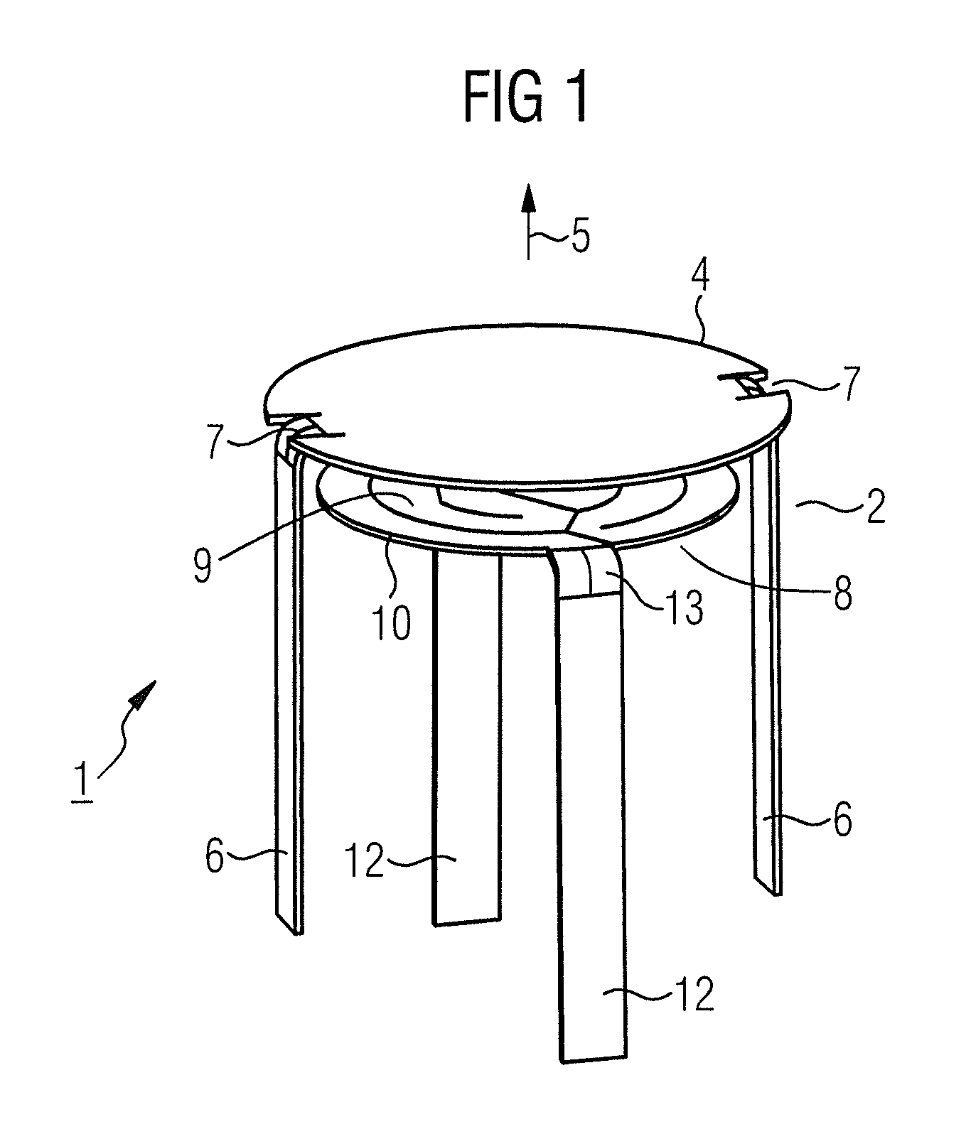
[0037]the primary emitter 2 is shown schematically in plan view in FIG. 2. The circular primary emission surface 4 is connected in the connection regions 7 with the terminal lugs 6 (covered in plan view).

second embodiment

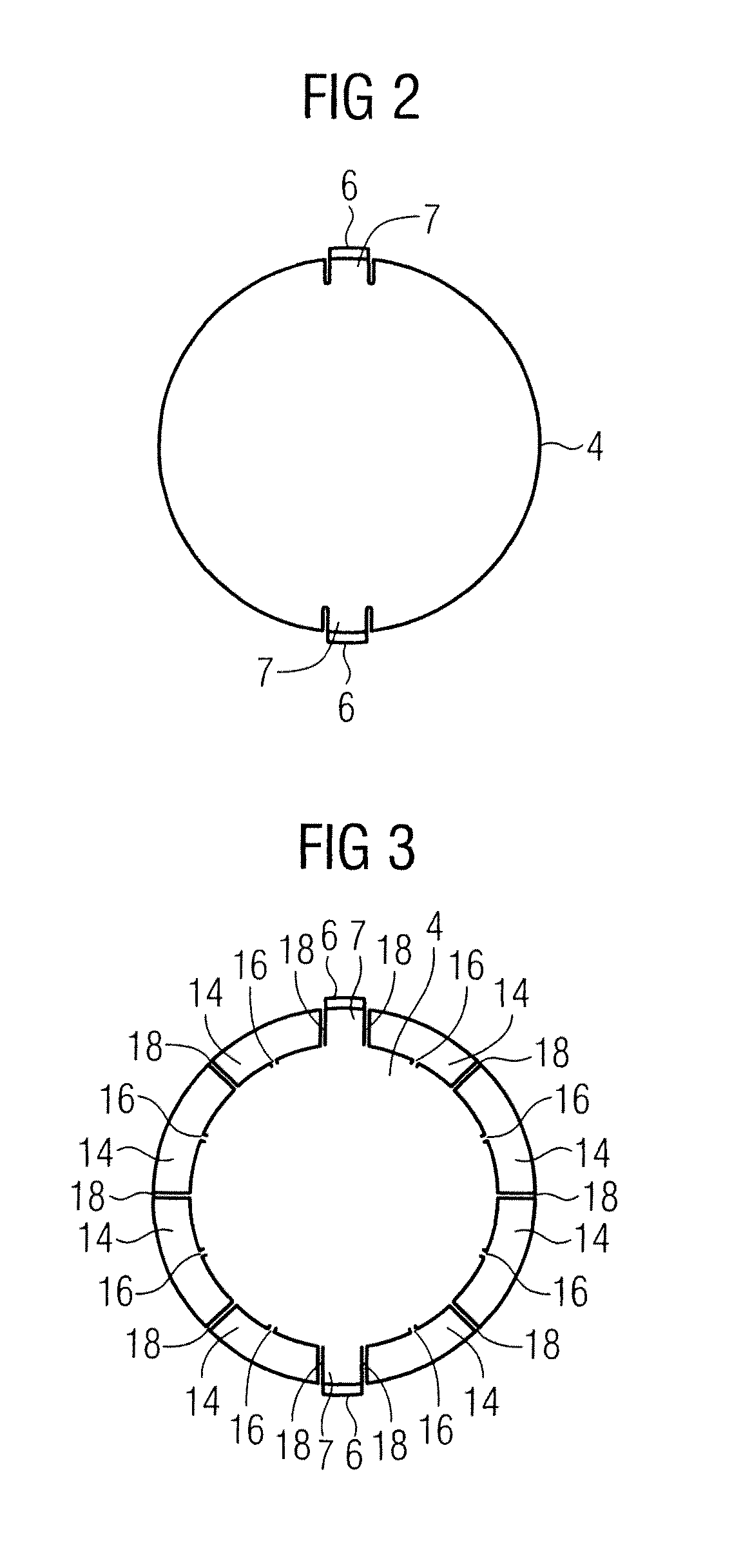
[0038]the primary emitter 2 is schematically shown in plan view in FIG. 3. The circular primary emission surface 4 is connected via webs 16 with segments 14 in the shape of circular ring segments 14. The segments 14 have no direct connection with one another and are separated from one another by gaps 18. The webs 16 are of designed such that a current flow from the primary emission surface 4 into the segments 14 is largely prevented so that the segments 14 do not heat and emit electrons. A bending of the electron paths corresponding to the electrons emitted from the outer edge of the primary emission surface 4 is prevented by the segments 14. Furthermore, the presence of the segments 14 reduces the possibility of electrons being emitted from the back side of the primary emission surface 4 facing away from the anode, that would be accelerated toward the anode and thus would enlarge the focal spot.

[0039]FIG. 4 shows in a lateral view a preferred variant of the thermionic emission devi...


PUM


Abstract

A thermionic emission device, in particular for use in an x-ray tube, has an indirectly heated primary emitter that is fashioned as a flat emitter with an unstructured primary emission surface, and a heating emitter that is fashioned as a flat emitter with a structured heat emission surface. The primary emitter and the heating emitter each has at least two terminal lugs, and the primary emission surface and the heat emission surface are aligned essentially parallel to one another. The emission device provides an optimally high quality of the focal spot with a simple design and, given high thermal load, an unwanted widening or defocusing of the electron beam is avoided by the terminal lugs of the primary emitter being aligned essentially perpendicular to the primary emission surface and not protruding beyond the primary emission surface in the lateral direction.

Description

BACKGROUND OF THE INVENTION[0001]1. Field of the Invention[0002]The present invention concerns a thermionic emission device (in particular for use in an x-ray tube) with an indirectly heated primary emitter that is fashioned as a flat emitter with an unstructured primary emission surface, and with a heating emitter that is fashioned as a flat emitter with a structured heat emission surface, wherein the primary emitter and the heating emitter respectively have at least two terminal lugs, and wherein the primary emission surface and the heat emission surface are aligned essentially parallel to one another.[0003]2. Description of the Prior Art[0004]A thermionic emission device of the above type, that is used as a cathode in an x-ray tube, is known from WO 2008 / 047269 A2. In this emission device an indirectly heated, unstructured, flat emission surface, having at least two fixing elements that lie in the plane of the emission surface and through which an electrical current can be conduc...

Claims


Application Information

Patent Timeline
Patent Type & Authority Patents(United States)
IPC IPC(8): H01J9/02
CPCH01J1/22H01J2235/06
Inventor FREUDENBERGER, JOERG
Owner SIEMENS HEALTHCARE GMBH
Why Eureka
Try Eureka