
Printing system and server therefor

a printing system and server technology, applied in the direction of digital output to print units, instruments, digital computers, etc., can solve the problems of frustration of each printing device in the system, inability to make the determination in an appropriate manner,

Active Publication Date: 2012-07-24
BROTHER KOGYO KK
View PDF10 Cites 0 Cited by
  • Summary
  • Abstract
  • Description
  • Claims
  • Application Information

AI Technical Summary

Benefits of technology

The present invention provides a printing system that can appropriately determine when a printing device needs to transfer its remaining number of printable sheets to another device to make up for a shortage. The server determines a transfer source based on the statuses of other devices, rather than just the device with the most remaining sheets. This helps to avoid frustration for users who may feel that their maximum number of printable sheets is repeatedly transferred from one device to another. The printing system also includes a server that can select the most appropriate device to transfer the remaining sheets based on the frequencies of printing operations performed by other devices. This results in a more efficient use of the printing devices in the system.

Problems solved by technology

Therefore, the determination is not necessarily made in an appropriate manner.
Consequently, it might cause a problem that a user of each printing device in the system feels frustrated because at least part of the maximum number of printable sheets is repeatedly transferred from one device to another.

Method used


Image

  • Printing system and server therefor
  • Printing system and server therefor
  • Printing system and server therefor

Examples


first embodiment

[0029][First Embodiment]

(1) Overall Configuration of Printing System

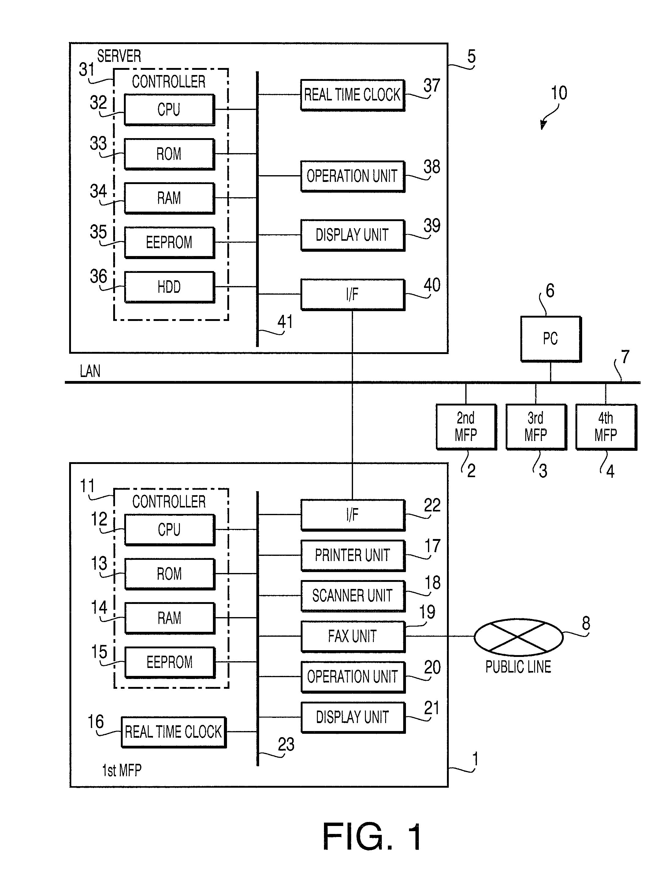
[0030]As illustrated in FIG. 1, a printing system 10 of a first embodiment includes a server 5, a first Multi-Function Peripheral (MFP) 1, a second MFP 2, a third MFP, a fourth MFP, and a Personal Computer (PC) 6, which are interconnected via a Local Area Network (LAN) 7 in a mutually communicable manner.

[0031]At first, a configuration of each of the MFPs 1 to 4 will be described. In the first embodiment, the MFPs 1 to 4 have the same configuration. Therefore, explanation will be provided here about the configuration of the first MFP 1 as a typical example, but not about the configurations of the other MFP 2 to 4.

[0032]The first MFP 1 has various functions such as a scanner function, a printer function, a facsimile function, and a network communication function. The first MFP 1 is provided with a controller 11, a clock 16, a printer unit 17, a scanner unit 18, a facsimile unit 19, an operation unit 20, a display uni...

second embodiment

[0113][Second Embodiment]

[0114]Subsequently, a printing system of a second embodiment will be described. A printing system of the second embodiment is different from the printing system 10 of the first embodiment in the print history information stored and managed on the EEPROM 15 of each of the MFPs 1 to 4 and the print history information stored and managed on the EEPROM 35 of the server 5. The above differences are accompanied by slight differences between the first embodiment and the second embodiment in the print control process to be executed by each of the MFPs 1 to 4 and the MFP management process to be executed by the server 5. Other configurations of the MFPs 1 to 4 and the server 5 are generally the same between the first embodiment and the second embodiment. Therefore, the following description will be provided, focusing on the differences of the second embodiment from the first embodiment.

(1) Transfer of Number of Printable Sheets between MFPs via Server

[0115]First, exp...


PUM


Abstract

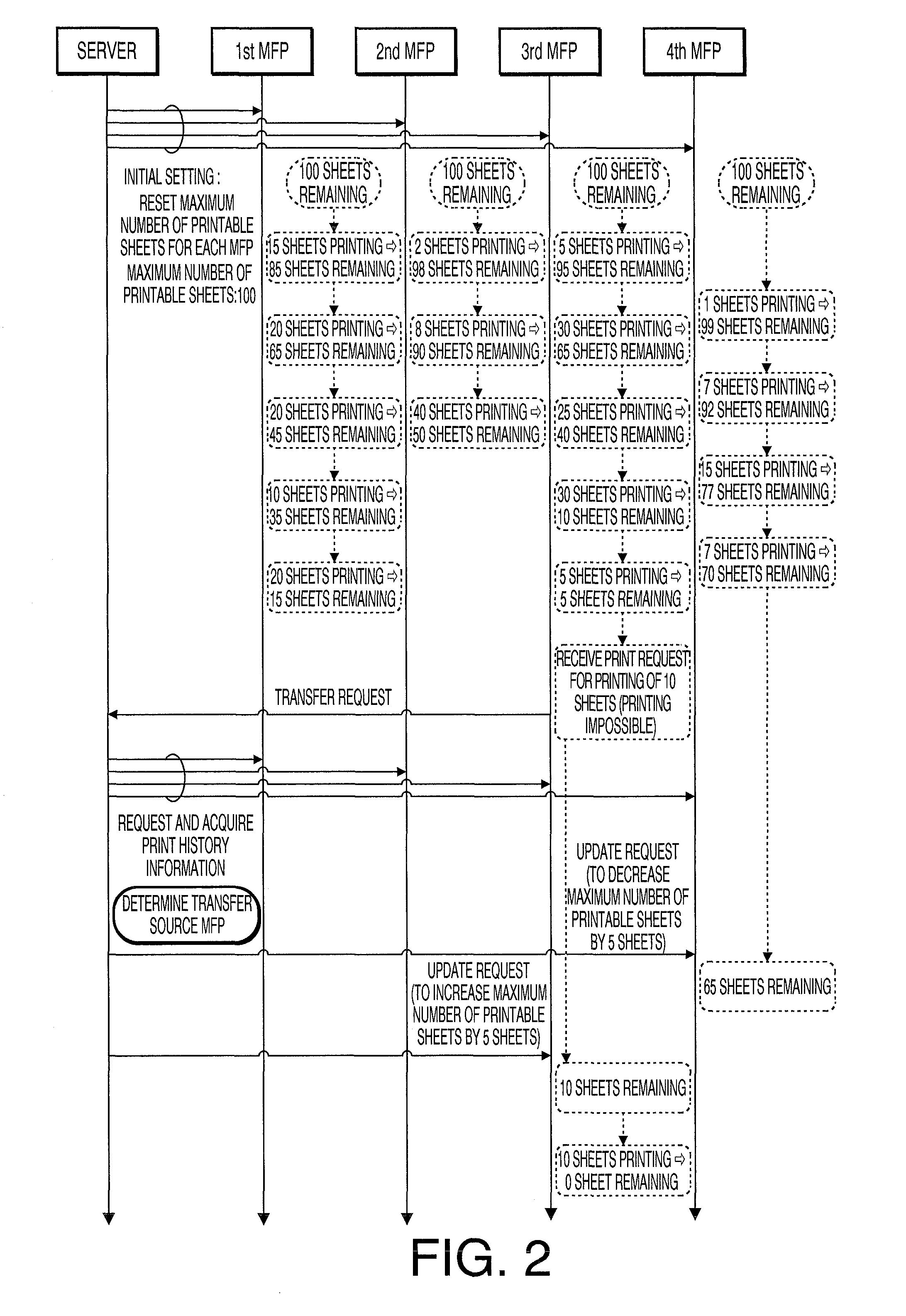
A printing system includes a server and a plurality of printing devices connected with the server via a network. A maximum number of printable sheets is set for each of the printing devices. Upon receipt of a print request, when determining that a remaining number of printable sheets is insufficient, a first printing device issues a transfer request to the server. In response to the transfer request, the server selects a second printing device that cedes at least part of the maximum number of printable sheets therefore, based on respective frequencies of printing operations of the printing devices other than the first printing device, and issues a transfer instruction to each of the first printing device and the second printing device, the transfer instruction causing the first and second printing devices to increase and decrease their maximum numbers of printable sheets, respectively.

Description

CROSS-REFERENCE TO RELATED APPLICATION[0001]This application claims priority under 35 U.S.C. §119 from Japanese Patent Application No. 2008-287805 filed on Nov. 10, 2008. The entire subject matter of the application is incorporated herein by reference.BACKGROUND[0002]1. Technical Field[0003]The following description relates to one or more printing system that includes a server and a plurality of printing devices interconnected via a network.[0004]2. Related Art[0005]So far, the following printing system has been known as an example of printing systems configured with a plurality of printing devices, interconnected via a network, for each of which a predetermined maximum number (an upper limit number) of printable sheets is set. In the printing system, when the number of sheets to be printed by a printing device exceeds the maximum number of printable sheets therefor, the printing device requests a different printing device to transfer at least part of the maximum number of printable...

Claims


Application Information

Patent Timeline
Patent Type & Authority Patents(United States)
IPC IPC(8): G06F3/12
CPCG06F3/1204G06F3/121G06F3/1226G06F3/126G06F3/1286G06F3/1288G06F3/1232G06F3/1261
Inventor YAMADA, AKIHIRO
Owner BROTHER KOGYO KK
Learn More