Method for controlling an automatic multi-step shift transmission

a transmission and multi-step technology, applied in the direction of digital data processing details, mechanical equipment, instruments, etc., can solve the disadvantages of motor noise when moving off the slope, unnecessarily high fuel consumption, and only insufficient driving force of the motor vehicle, so as to achieve less noise and reduce fuel consumption

Active Publication Date: 2012-07-24
ZF FRIEDRICHSHAFEN AG
View PDF19 Cites 5 Cited by
  • Summary
  • Abstract
  • Description
  • Claims
  • Application Information

AI Technical Summary

Benefits of technology

[0009]Accordingly, the purpose of the present invention is to indicate a method for controlling an automatic multi-step shift transmission of the type mentioned at the start, by virtue of which the shifting behavior of the multi-step shift transmission during the run-out from a downward slope can be improved in relation to lower fuel consumption and less emission of noise.
[0011]Thus, a thrust upshift is carried out while still driving downhill. In this way the speed of the drive motor and of a primary retarder, if present, are reduced by the transmission ratio interval between the previously engaged lower gear and the currently engaged higher gear. Besides reducing the noise emissions of the drive motor and the multi-step shift transmission, this results in a reduction of the drive motor's drag torque and of the braking torque of the primary retarder. Consequently, as the motor vehicle drives through the downhill run-out it accelerates at least slightly because of the overall smaller braking forces in thrust operation, so that compared with previous control processes the transition to traction operation when it then moves onto level ground takes place substantially later. Due to this, especially when the profile of the stretch of road traveled has frequent changes between hilly and level sections, considerable fuel savings can be achieved. Moreover, thanks to such automatically initiated upshifts, the driver does not have to keep selecting the optimum gear and can therefore concentrate better on observing the traffic situation.
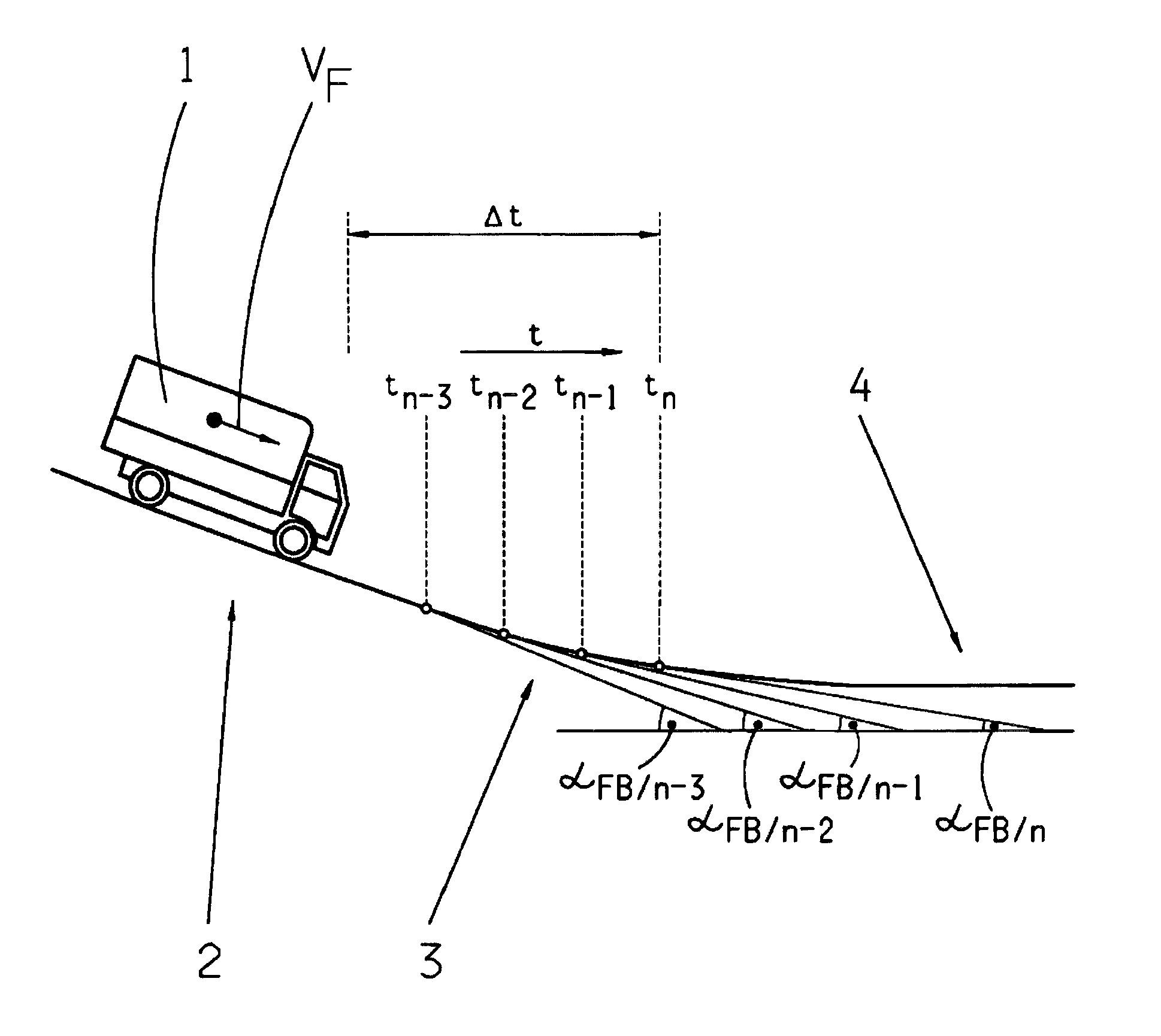
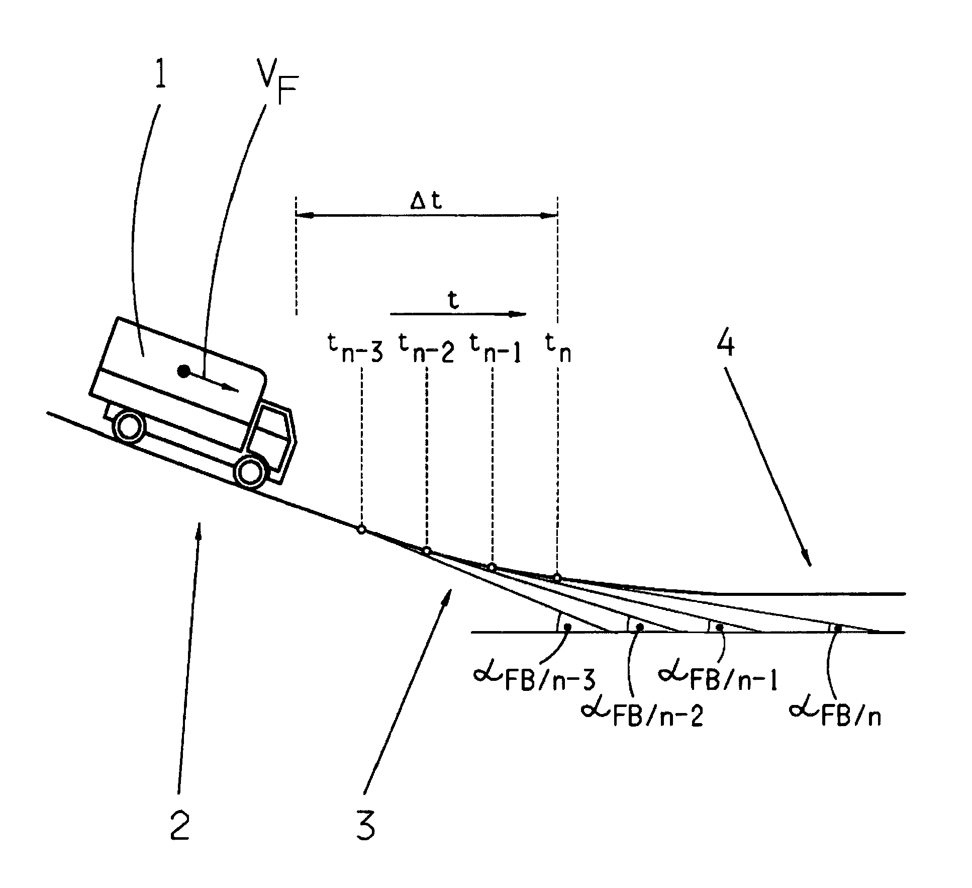
[0013]The higher gear to which the automatically initiated thrust shift takes place, is expediently determined as a function of the current driving resistance Fw in such manner that the driving acceleration aF / erw to be expected in the gear does not exceed a predetermined acceleration limit value aGr (aF / erw≦aGr). This ensures that in the higher gear the motor vehicle does not accelerate to an extent that takes the driver by surprise and may possibly be dangerous, but that it accelerates in a manner that can be safely controlled by actuating the brakes if needs be.
[0015]Consequently, the thrust upshift is expediently prevented if, within the time interval Δt considered, an actuation of the service brake has been detected, which can for example be determined by means of a brake pedal sensor with reference to brake pedal movement xBP>0 and / or by means of a brake pressure sensor of the service brake with reference to brake pressure pBr>0. By actuating the service brake the driver indicates a wish to slow down the motor vehicle, for example because of corresponding events observed in the surrounding traffic, so that this driver's wish would counteract an acceleration resulting from the thrust upshift provided for as such, and to compensate the smaller braking effect of the drive motor, a correspondingly more powerful actuation of the service brake would be required.
[0019]The two above-mentioned operating conditions for suppressing the thrust upshift can also be combined, in that the thrust upshift is prevented if the driving resistance F, determined during the time interval Δt considered has fallen below a lower (negative) limit value of the resistance FGr / u (Fw<FGr / u). As is known, a steep downhill road gradient αFB<0 and a large vehicle mass mFzg result in a large downhill driving force and thus to a small, i.e. negative driving resistance FW<0 which propels the motor vehicle, and it is then expedient for the reasons mentioned earlier to suppress the thrust upshift provided for as such.
[0020]If a permanent brake such as a primary retarder coupled to the input shaft of the multi-step shift transmission or a secondary retarder coupled to its output shaft is activated, then it is also appropriate to suppress the thrust upshift as a function of the current capacity loading of the permanent brake. Consequently, the thrust upshift is prevented if, when the permanent brake is activated, the current braking torque MDBr of the permanent brake has exceeded an upper limit related to the maximum braking capacity MDBr<sub2>—< / sub2>max of the permanent brake (for example 80% of the maximum braking capacity; factor=0.8) (MDBr>0.8*MDBr<sub2>—< / sub2>max), i.e. the permanent brake is being operated close to its load limit. In this way the speed-dependent braking capacity MDBr<sub2>—< / sub2>max of the permanent brake is not reduced by a thrust downshift and if a downhill stretch comes after the recognized downhill run-out, a sufficiently large capacity reserve of the permanent brake is available in case it is necessary to slow down the motor vehicle even more.

Problems solved by technology

The disadvantage of an upshift that takes place only after moving onto level ground or after the transition to traction operation, is that the momentum of the motor vehicle, i.e. the driving force due to the slope, is used only insufficiently when moving off the slope to propel the motor vehicle while it is moving off the slope and at the beginning of the subsequent driving on level ground or on a new uphill stretch.
Due to this the thrust operation ends relatively early and fuel injection is switched on again, which results in unnecessarily high fuel consumption.
Furthermore owing to the high engine speed caused by the lower gear, the noise level produced by the motor when moving off the slope is disadvantageously high.

Method used


Image

  • Method for controlling an automatic multi-step shift transmission
  • Method for controlling an automatic multi-step shift transmission

Examples


Embodiment Construction

[0024]In the schematic representation of the sole FIGURE a motor vehicle 1 is driving on a downhill stretch 2 at a speed vF, so that the drive motor is in thrust operation and a retarder, if present, is engaged. At the latest after driving onto the downhill stretch 2 and / or after the transition to thrust operation, a recognition function for determining a downhill run-out 3 between the current downhill stretch 2 and a subsequent stretch of level ground 4 is initiated in an electronic control unit.

[0025]Within the recognition function, in a set time cycle ti, ti+1, ti+2, . . . the respective current road gradients αFB / i, αFB / i+1, αFB / i+2, . . . , i.e. the downhill or uphill gradients of the road are determined. If then, at a specified number of consecutive and immediately previous time points, in this case for example four time points tn−3, tn−2, tn−1, tn, the road gradient αFB / i determined has been decreasing monotonically in its absolute numerical value, i.e. |αFB / n|FB / n−1|FB / n−2|F...


PUM


Abstract

A method of controlling an automatic transmission of a motor vehicle that is situated in the force flow between a drive motor and an axle drive of a drive axle or a transfer box in which the current road inclination (αFB) is determined. To improve the shifting behavior of the transmission, during a transition between driving on a downhill stretch (2) and on level ground (4), after driving on the downhill stretch (2) and / or after the transition to a thrust operation, a recognition function for determining a downhill run-out (3) is initiated and, when the downhill run-out (3) is recognized, a shift to a higher gear during a thrust operation, i.e., a thrust upshift, is carried out before driving onto level ground (4) and / or before the transition to the traction operation.

Description

[0001]This application is a National Stage completion of PCT / EP2008 / 062010 filed Sep. 11, 2008, which claims priority from German patent application serial no. 10 2007 044 432.1 filed Sep. 18, 2007.FIELD OF THE INVENTION[0002]The invention concerns a method for controlling an automatic multi-step shift transmission arranged in a drivetrain of a motor vehicle, for example a utility vehicle, in the force flow between a drive motor in the form of an internal combustion engine and an axle drive of a drive axle or a transfer box, in which method the current road inclination is determined.BACKGROUND OF THE INVENTION[0003]In the case of a motor vehicle fitted with an automatic multi-step shift transmission such as an automated change-speed transmission, an automated dual-clutch transmission or a converter automatic transmission, after driving onto a downward-sloping stretch a lower gear is engaged, in order to increase the speed of the drive motor which, after the transition to thrust oper...

Claims


Application Information

Patent Timeline
Patent Type & Authority Patents(United States)
IPC IPC(8): G06F7/00G06F17/00G06F19/00
CPCF16H61/0213F16H61/21F16H59/66F16H2061/0234
Inventor WINKEL, MATTHIAS
Owner ZF FRIEDRICHSHAFEN AG
Why Eureka
Try Eureka