Modular transvane assembly

a transvane and module technology, applied in the direction of machines/engines, liquid fuel engines, lighting and heating apparatus, etc., can solve the problems of increasing gas flow loss through seals, reducing the amount of energy present, and requiring substantial cooling

Active Publication Date: 2012-07-31
SIEMENS ENERGY INC
View PDF16 Cites 22 Cited by
  • Summary
  • Abstract
  • Description
  • Claims
  • Application Information

AI Technical Summary

Problems solved by technology

Configurations of this nature reduce the amount of energy present in the gas flow as the flow travels toward the first row of turbine blades, and inherently require substantial cooling.
Gas flow loss through seals increases as seals wear due to vibration and ablation.
Significant energy is also lost when the flow is redirected by the vanes.
These configurations thus create inefficiencies in the flow which reduce the ability of the gas flow to impart rotation to the first row of turbine blades.
The cooled components are expensive and complicated to manufacture due to the cooling structures, exacting tolerance requirements, and unusual shapes.
Layers of thermally insulated or such cooled components may wear and can be damaged, which requires repair or replacement, which creates costs in terms of materials, labor, and downtime.
Thermal stresses also reduce the service life of the underlying materials.
This requires energy and creates more opportunities for heat related component damage and associated costs.
This requires additional seals between the vane components, through which there is more gas flow loss.
Further, these configurations usually require assembly of the components directly onto the engine in confined areas of the engine, which is time consuming and difficult.

Method used


Image

  • Modular transvane assembly
  • Modular transvane assembly
  • Modular transvane assembly

Examples


Embodiment Construction

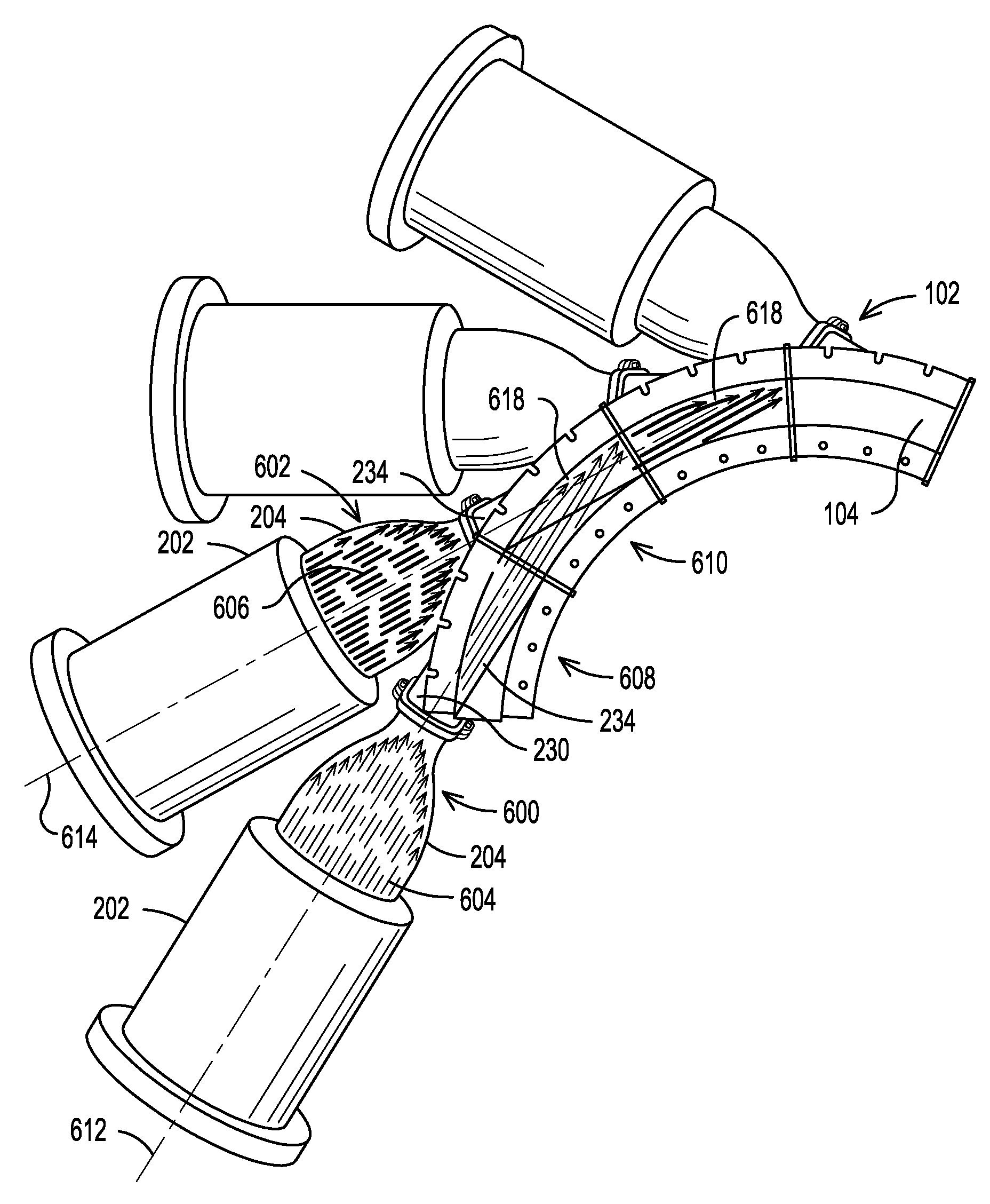
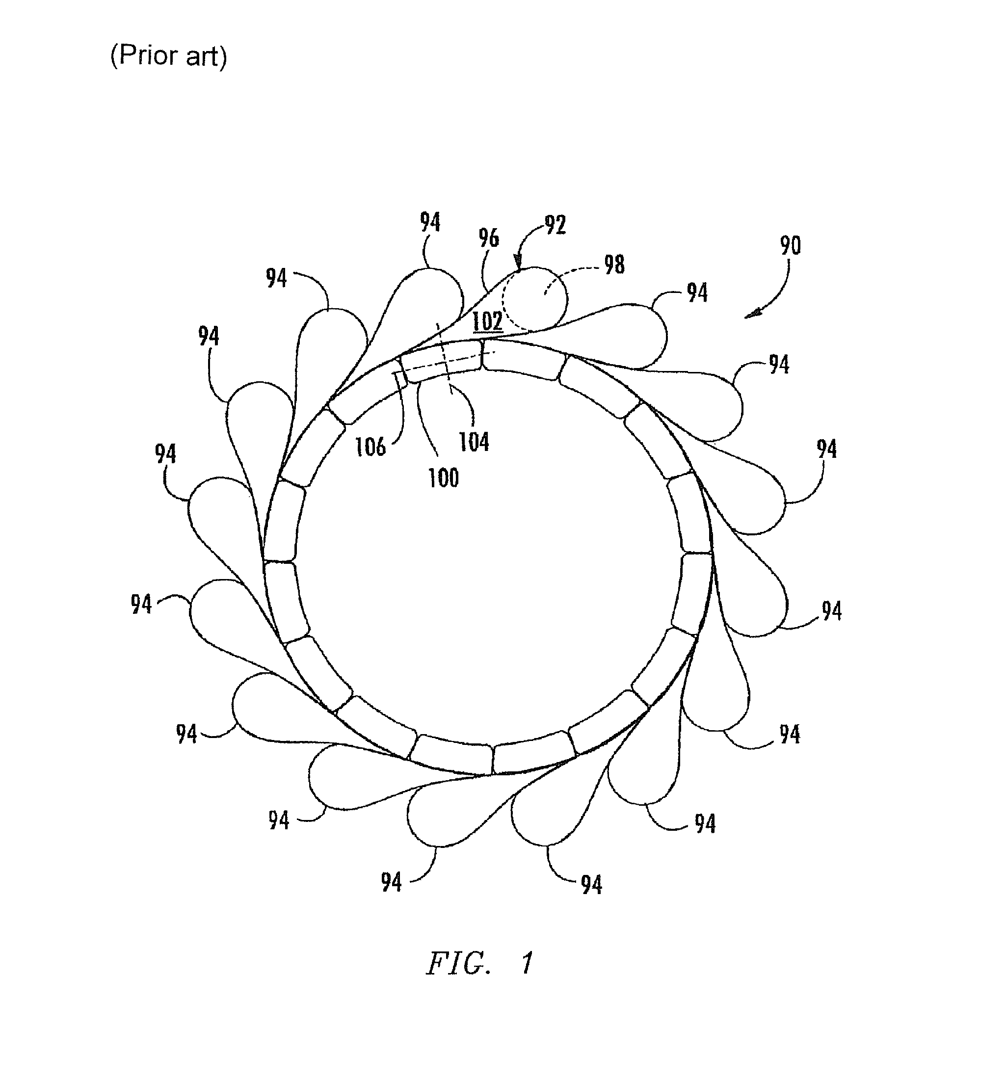
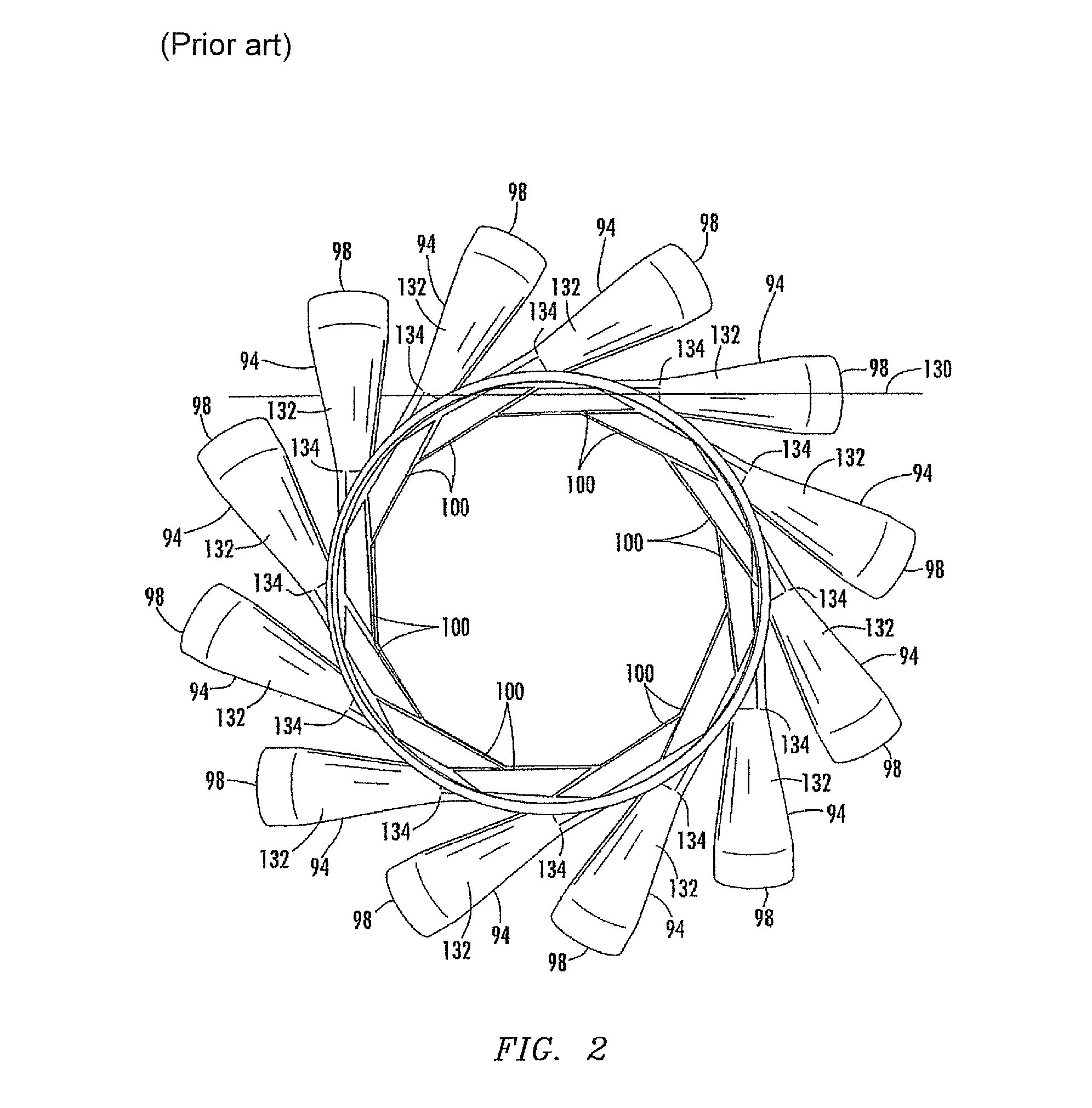
[0024]The inventors of the present system have designed an innovative arrangement, made of multiple, modular, interchangeable, transvane assemblies which direct and then combine individual gas flows from the cans of a can annular combustor of a gas turbine combustion engine into a singular annular gas flow with a circumferential component to the flow, which is then directed to the first row of turbine blades. The inventors of the present system observed that prior configurations for delivering flows of can-annular combustors to the first row of turbine blades kept each flow separate and distinct from the other flows all the way to the first row of turbine blades. As a result, between each flow about to contact the first row of turbine blades there is a gap, or trailing edge, where there is reduced or no flow delivered to the blades. These trailing edges, which vary in magnitude from design to design, create flow disturbances and associated energy losses. Consequently, as the first r...


PUM


Abstract

An arrangement for delivering gasses from can combustors of a can annular gas turbine combustion engine to a turbine first stage section including a first row of turbine blades, the arrangement including a flow-directing structure for each combustor, wherein each flow-directing structure includes a straight path and an annular chamber end, wherein the annular chamber ends together define an annular chamber for delivering the gas flow to the turbine first stage section, wherein gasses flow from respective combustors, through respective straight paths, and into the annular chamber as respective straight gas flows, and wherein the annular chamber is configured to unite the respective straight gas flows along respective shear planes to form a singular annular gas flow, and wherein the annular chamber is configured to impart circumferential motion to the singular annular gas flow before the singular annular gas flow exits the annular chamber to the first row of blades.

Description

[0001]This application claims benefit of the 29 Sep. 2008 filing date of U.S. provisional application No. 61 / 100,853.FIELD OF THE INVENTION[0002]This invention relates to gas turbine combustion engines. In particular, this invention relates to an assembly for transporting expanding gasses to the first row of turbine blades.BACKGROUND OF THE INVENTION[0003]Gas turbine combustion engines with can annular combustors require structures to transport the gasses coming from the combustors to respective circumferential portions of the first row of turbine blades, hereafter referred to simply as the first row of turbine blades. These structures must orient the flow of the gasses so that the flow contacts the first row of turbine blades at the proper angle, to produce optimal rotation of the turbine blades. Conventional structures include a transition, a vane, and seals. The transition transports the gasses to the proper location and directs the gasses into the vanes, which orient the gas flo...

Claims


Application Information

Patent Timeline
Patent Type & Authority Patents(United States)
IPC IPC(8): F02C3/00
CPCF23R3/425F23R3/46F01D9/023F05D2240/40F05D2250/323F05D2250/121F05D2250/141F05D2250/322F05D2250/324
Inventor WILSON, JODY W.NORDLUND, RAYMOND S.CHARRON, RICHARD C.
Owner SIEMENS ENERGY INC
Why Eureka
Try Eureka