
Method of operating a fuel cell stack

Active Publication Date: 2012-07-31
GM GLOBAL TECH OPERATIONS LLC
View PDF7 Cites 0 Cited by
  • Summary
  • Abstract
  • Description
  • Claims
  • Application Information

AI Technical Summary

Benefits of technology

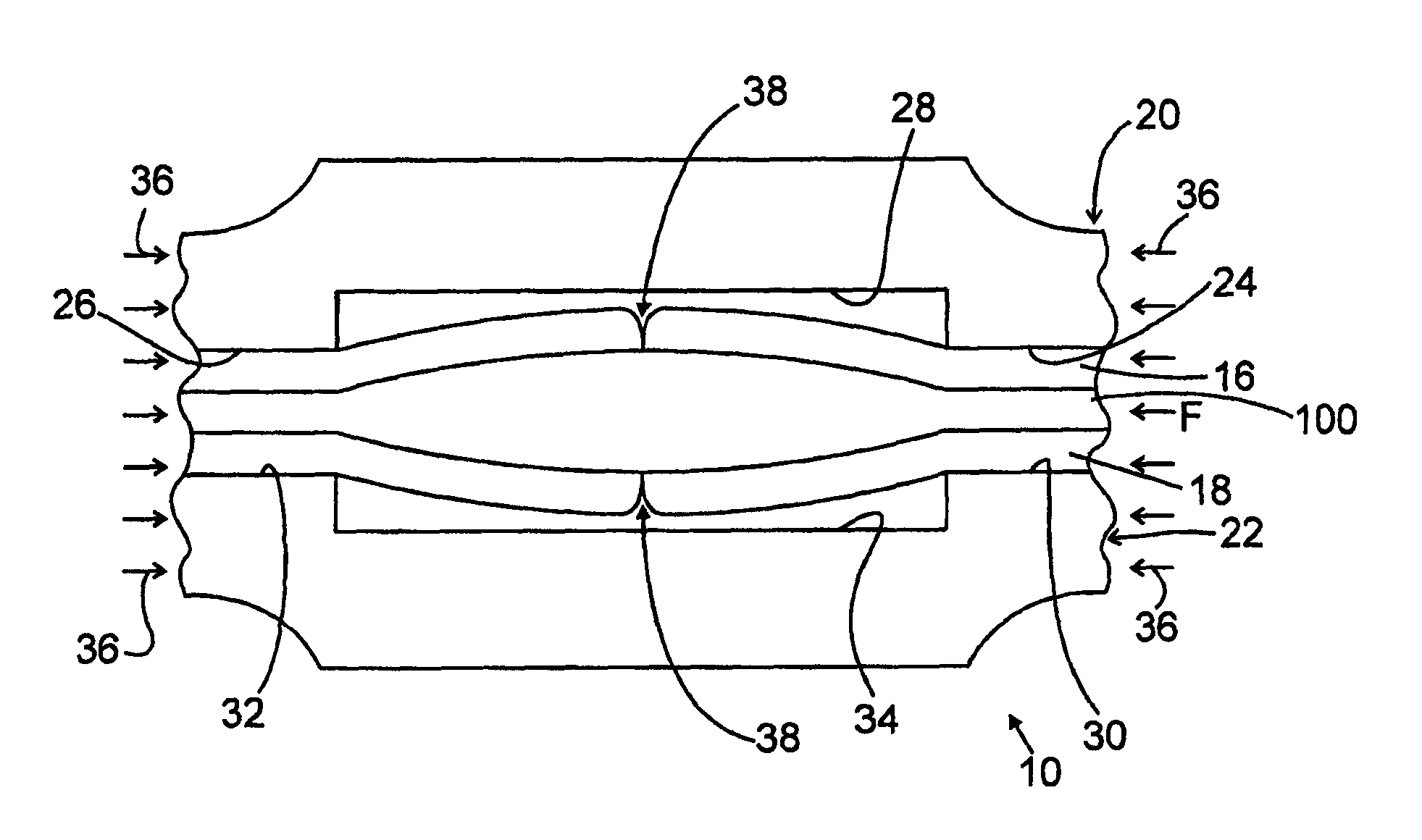
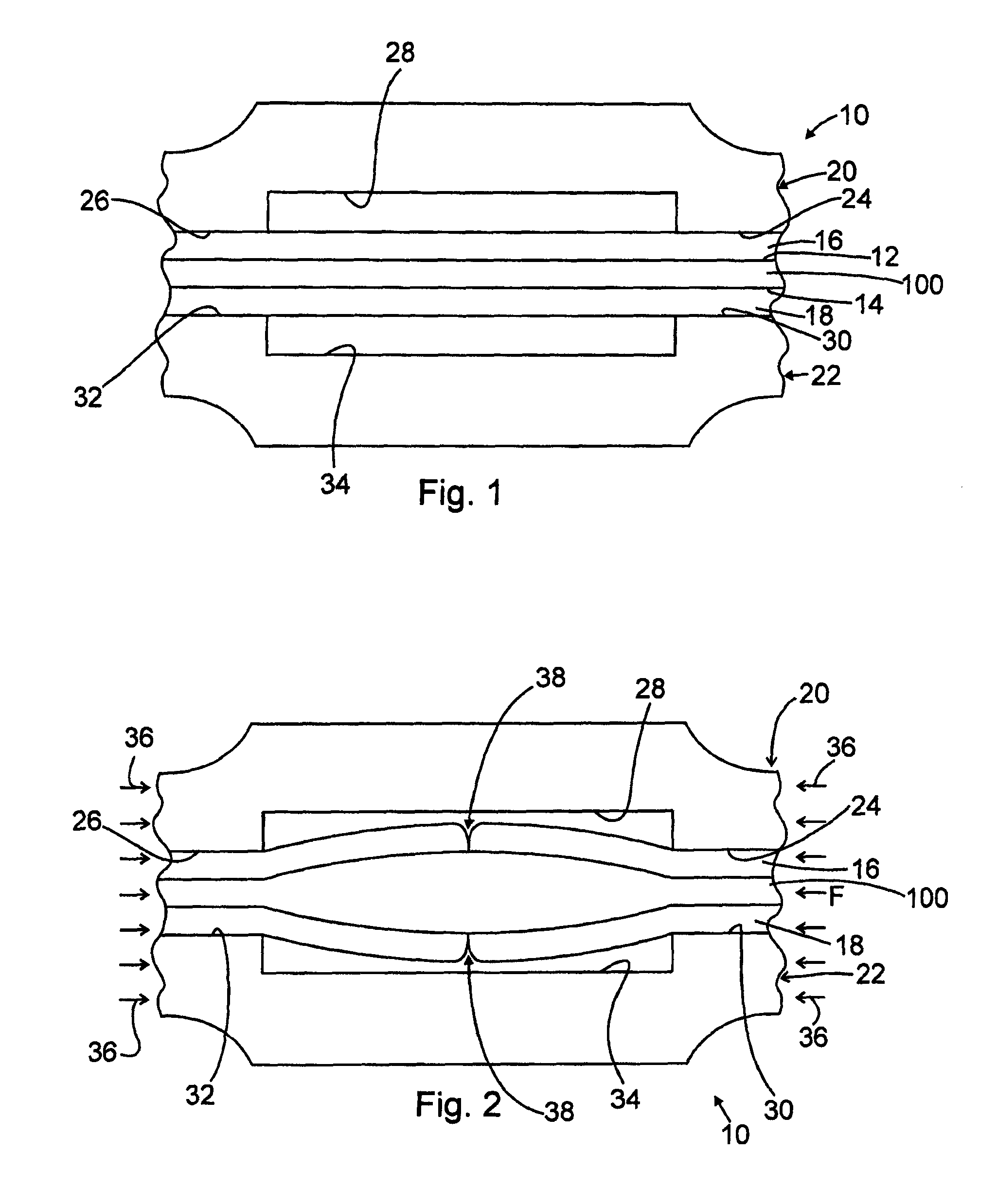
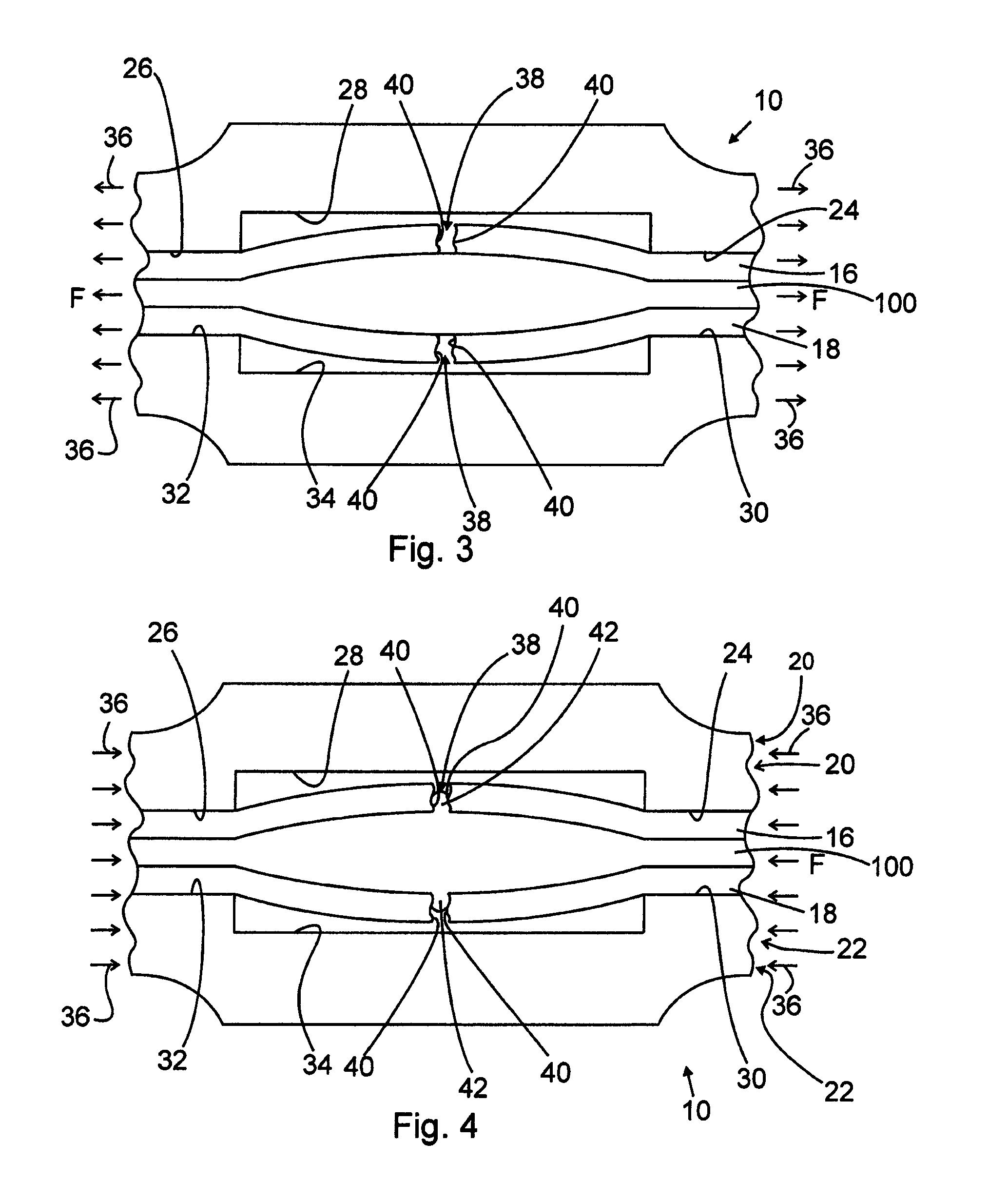
[0004]One embodiment of the invention includes the discovery that pinholes in the membrane of the membrane electrode assembly may be caused by hygroexpansive ratcheting. In one embodiment of the invention includes a fuel cell stack including a plurality of cells each having a membrane electrode assembly each including a membrane manufactured by an extrusion method and operated so that the rate of drying during humidity cycling is sufficiently low to reduce or eliminate the build up of stresses in the membrane electrode assembly. In one embodiment, the rate of drying δλ / δ time is less than 0.2 λ / sec. Lamda (λ) as used herein is defined as the number of water molecules per unit proton in the ionomer (H2O / H+)—physically, it is the level of hydration.
[0011]One embodiment of the invention includes operating the fuel cell stack under conditions that minimize chemical thinning of the ionomer in the membrane via peroxide-induced free radical depolymerization. In one embodiment of the invention the fuel cell stack is operated so as to minimize cycling to high potentials such as 300 mV of OCV under low membrane humidification.
[0012]Another embodiment of the invention minimizes any gap between the catalyst layer of a membrane electrode assembly and a protective layer or gasket layer to less than 50 microns.
[0014]Another embodiment of the invention includes compressing the compressible components of the fuel cell uniformly so that the membrane electrode assembly is prevented from buckling between the lands of bipolar plates.

Problems solved by technology

One of the key challenges in the race to commercialize fuel cells for vehicle applications is developing membrane electrode assemblies (MEAs) that can meet industry durability targets.
Fuel cells cannot operate effectively if even small amounts of these gases are allowed to permeate through the membrane through, for example, microscopic pinholes in the membrane.
Ultimately, fuel cells fail because such pinholes develop and propagate within the polymer membranes.

Method used


Image

  • Method of operating a fuel cell stack
  • Method of operating a fuel cell stack
  • Method of operating a fuel cell stack

Examples


Embodiment Construction

[0004]One embodiment of the invention includes the discovery that pinholes in the membrane of the membrane electrode assembly may be caused by hygroexpansive ratcheting. In one embodiment of the invention includes a fuel cell stack including a plurality of cells each having a membrane electrode assembly each including a membrane manufactured by an extrusion method and operated so that the rate of drying during humidity cycling is sufficiently low to reduce or eliminate the build up of stresses in the membrane electrode assembly. In one embodiment, the rate of drying δλ / δ time is less than 0.2 λ / sec. Lamda (λ) as used herein is defined as the number of water molecules per unit proton in the ionomer (H2O / H+)—physically, it is the level of hydration.

[0005]In one embodiment of the invention a fuel cell stack includes a membrane electrode assembly and bipolar plates constructed and arranged so that the planar aerial hygroexpansion of the membrane is less than 25% during a humidity cycle ...


PUM


Abstract

One aspect of the invention includes the discovery that pinholes in the membrane of the membrane electrode assembly may be caused by hygroexpansive ratcheting. In one embodiment of the invention, a fuel cell stack including a plurality of cells each having a membrane electrode assembly each including a membrane manufactured by an extrusion method and operated so that the rate of drying during humidity cycling is sufficiently low to reduce or eliminate build up stresses in the membrane electrode assembly.

Description

CROSS-REFERENCE TO RELATED APPLICATIONS[0001]This Application claims the benefit of U.S. Provisional Application No. 60 / 731,804 filed Oct. 31, 2005.TECHNICAL FIELD[0002]The present invention relates to a method, and more particularly, to a method of operating a fuel cell stack.BACKGROUND[0003]One of the key challenges in the race to commercialize fuel cells for vehicle applications is developing membrane electrode assemblies (MEAs) that can meet industry durability targets. Polymer electrolyte membranes (PEMs) are the most promising membranes for automotive applications. These membranes serve to conduct protons from the anode electrode to the cathode electrode of the fuel cell while preventing the crossover of reactant gases, hydrogen and oxygen. State-of-the-art PEM fuel cells for high power density operations utilize perfluorosulfonic acid (PFSA) membranes that are typically about 25 microns thick or less. To be successful in automotive applications, these membranes must survive t...

Claims


Application Information

Patent Timeline
IPC IPC(8): H01M8/06H01M8/10H01M8/04H01M50/571
CPCH01M4/8657H01M8/04291H01M8/1004H01M8/1016H01M8/241H01M8/0247H01M8/026H01M8/04164H01M8/04223H01M8/04253H01M8/04313H01M8/04365H01M8/04529H01M8/04731H01M8/0485H01M8/248H01M2300/0082H01M2300/0094Y02E60/521Y02P70/50Y02E60/50H01M8/0258
Inventor BUDINSKI, MICHAEL K.GITTLEMAN, CRAIG S.LAI, YEH-HUNGLEWIS, CHRISTOPHERMILLER, DANIEL
Owner GM GLOBAL TECH OPERATIONS LLC
Learn More