Image processing apparatus, image processing method, and imaging apparatus

a technology of image processing apparatus and image processing method, which is applied in the field of image processing apparatus, image processing method, imaging apparatus, can solve the problems of further deterioration of signal components, and achieve the effects of strong intra-screen noise reduction, favorable noise reduction effect, and strong noise reduction

Active Publication Date: 2012-07-31
SONY CORP
View PDF7 Cites 9 Cited by
  • Summary
  • Abstract
  • Description
  • Claims
  • Application Information

AI Technical Summary

Benefits of technology

[0019]Now, with intra-screen NR processing, a pixel value wherein the correlation value (absolute value of difference, etc) between the two pixels of the pixel of interest within the window region and other periphery pixels that is at or below a threshold θth is selected and averaging processing is performed, thereby reducing noise.
[0042]According to the above configuration, signal components are restored in the image adding while performing strong intra-screen noise reduction, and an image output is obtained with favorable noise reduction effects.

Problems solved by technology

Even if adding of multiple imaged images is performed with addition NR processing, the suppressed signal components are not recovered, whereby there are cases wherein signal components are further deteriorated.

Method used


Image

  • Image processing apparatus, image processing method, and imaging apparatus
  • Image processing apparatus, image processing method, and imaging apparatus
  • Image processing apparatus, image processing method, and imaging apparatus

Examples


first example

SAD Value Correction by Adding Offset

[0322]FIG. 26 is a diagram to describe the thinking in the first example. FIG. 26 is a diagram showing the SAD table content (SAD value) for one target block when the horizontal axis is taken as the search range and the vertical axis is taken as the SAD value. The various values of the vertical axis is a reference block position (reference vector), and the solid line shows the content of the SAD table. This is completely the same as that shown in FIG. 17.

[0323]In FIG. 26, the position 501 of the reference block (i.e. reference vector) serving as the minimum SAD value is detected by the block matching as a local motion vector LMV, similar to FIG. 17. On the other hand, the position of the reference block serving as the global motion vector GMV is position 503 in FIG. 26.

[0324]At this time, if the SAD value of the local motion vector LMV and the SAD value of the global motion vector GMV are in a range of differences according to the amount of noise...

second example

Correction of SAD Value by Gain Multiplication

[0365]In the above-described first example, the SAD value SAD_GMV is corrected for the reference block of the reference vector position matching the global motion vector GMV by the addition of the offset value OFS.

[0366]Similarly, the SAD value SAD_GMV can also be corrected by multiplying gain g that takes into account the amount of image noise, instead of adding the offset. In the case of this example, the SAD value SAD_GMV is multiplied by the amount of gain in the direction of getting smaller, whereby gain g becomes g1.

The post-correction SAD value MinSAD_G of the SAD value SAD_GMV with the global motion vector GMV becomes the expression

MinSAD—G=SAD_GMV×g  (Expression 9)

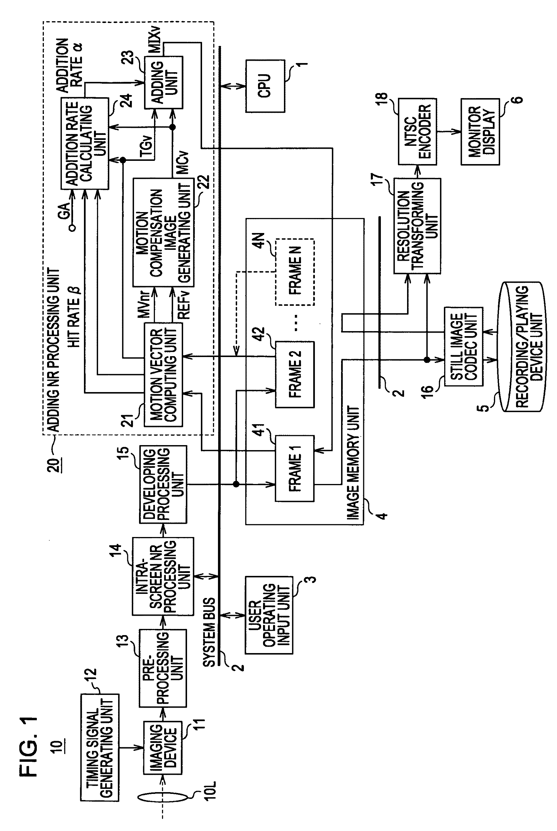
Configuration Example of Adding Rate Calculating Unit 24

[0367]According to the present embodiment, the adding rate calculating unit 24 obtains an adding rate α (0≦α≦1) in pixel increments. As described above, basically, the adding rate α in accordance with the differen...

other embodiment and modified example

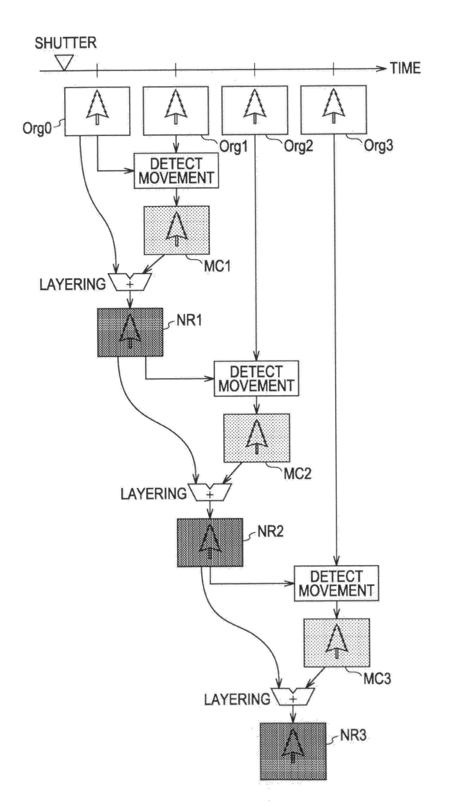
[0456]In the case of performing adding NR processing for the still image, there may be various examples such as how to set selection of the target image and reference images, or in what sequence to layer the images.

[0457]In the case of layering multiple images, an image that becomes the standard for motion detection has to be selected. With the above-described embodiment, the image at the moment of the shutter being closed is the image desired by the user, whereby the first imaged image is set to be the standard image. That is to say, the user releases the shutter, and using an image shot later in time, performs layering as to the first image that is shot.

[0458]The above-described adding method sets the NR image as a result of layering the target image and reference image to be the next target image, and in the second image layering and thereafter, the target image becomes an image that has been subjected to constant NR processing. This adding method is called a target adding method...


PUM


Abstract

An image processing apparatus includes an image adding unit to perform noise reduction processing in the spatial direction by adding multiple images while performing motion compensation, an intra-screen noise reducing unit to perform noise reduction processing in the spatial direction within one image for each of the multiple images before adding with the image adding unit, and a control unit to vary the noise reduction strength in the spatial direction by the intra-screen noise reduction unit as to the multiple images to be added with the image adding unit.

Description

CROSS-REFERENCE TO RELATED APPLICATION[0001]The present application claims priority from Japanese Patent Application No. JP 2009-012556 filed in the Japanese Patent Office on Jan. 23, 2009, the entire content of which is incorporated herein by reference.BACKGROUND OF THE INVENTION[0002]1. Field of the Invention[0003]The present invention relates to an image processing apparatus, image processing method, and imaging apparatus to enable noise reduction in an image that has been imaged with an imaging device, for example.[0004]2. Description of the Related Art[0005]For example, with an imaging apparatus such as a digital still camera or the like, various types of methods have been provided heretofore as methods to reduce noise in an imaged image. For example, in Japanese Unexamined Patent Application Publication No. 2008-177801 is disclosed a method of noise reduction processing in the spatial direction within one imaged image (hereafter this noise reduction processing will be referred...

Claims


Application Information

Patent Timeline
Patent Type & Authority Patents(United States)
IPC IPC(8): H04N5/217G06T5/00G06T5/20H04N5/232H04N5/91H04N101/00
CPCG06T5/50H04N1/2145H04N5/217G06T5/002G06T2207/20216H04N5/144H04N5/772H04N2101/00H04N2201/0084G06T2207/20192H04N23/81
Inventor MITSUYA, KOJIKURATA, TOHRUMATSUSHITA, NOBUYUKI
Owner SONY CORP
Why Eureka
Try Eureka