Thermal instrument engine

a technology of instrument engine and thermal instrument, which is applied in the direction of instruments, optical radiation measurement, television systems, etc., can solve the problems of heat shutter, individual pixels exhibiting fixed pattern noise over extended lengths of time, and fixed pattern nois

Active Publication Date: 2012-08-07
JOHN FLUKE MFG CO INC
View PDF19 Cites 13 Cited by
  • Summary
  • Abstract
  • Description
  • Claims
  • Application Information

AI Technical Summary

Problems solved by technology

These non-uniformities often result in fixed pattern noise.
In particular, the change in temperature of the camera's internal components, e.g., due to self-heating or as the result of changes to the surrounding ambient temperature, leads to the individual pixels exhibiting fixed pattern noise over extended lengths of time.
Such energy may heat the shutter.
In addition, the solenoid that actuates the shutter between its open and closed positions may heat up the shutter if the solenoid is frequently used.
A change in shutter temperature may negatively impact the offset compensation functionality, resulting in poor imaging capabilities.
It is believed that past infrared cameras have not accurately tracked changes in the shutter temperature.
Past infrared camera designs have not provided such sensors in a compact, cost-effective manner.

Method used


Image

  • Thermal instrument engine
  • Thermal instrument engine
  • Thermal instrument engine

Examples


Embodiment Construction

[0022]The following detailed description is exemplary in nature and is not intended to limit the scope, applicability, or configuration of the invention in any way. Rather, the following description provides practical illustrations for implementing exemplary embodiments of the invention.

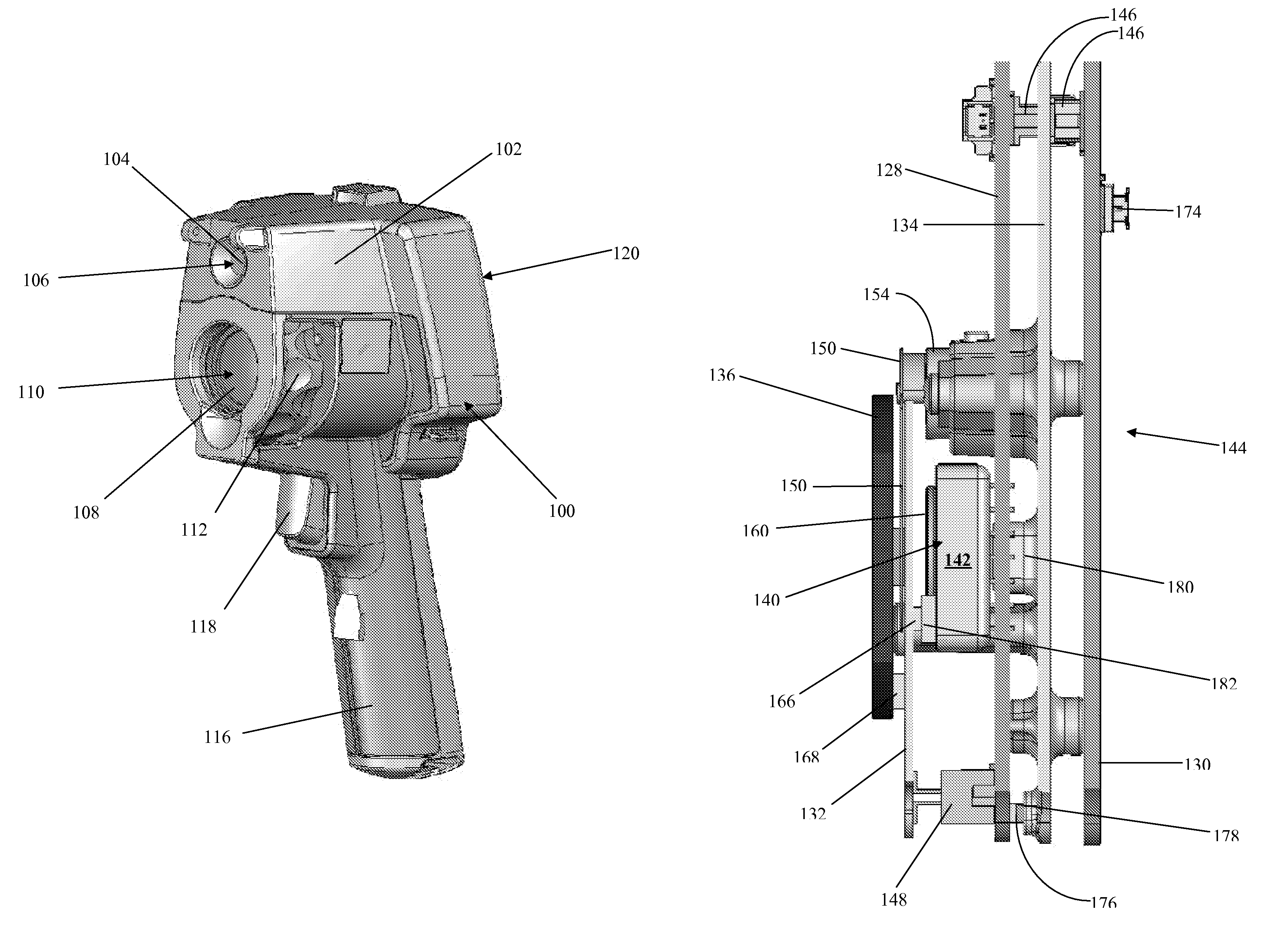
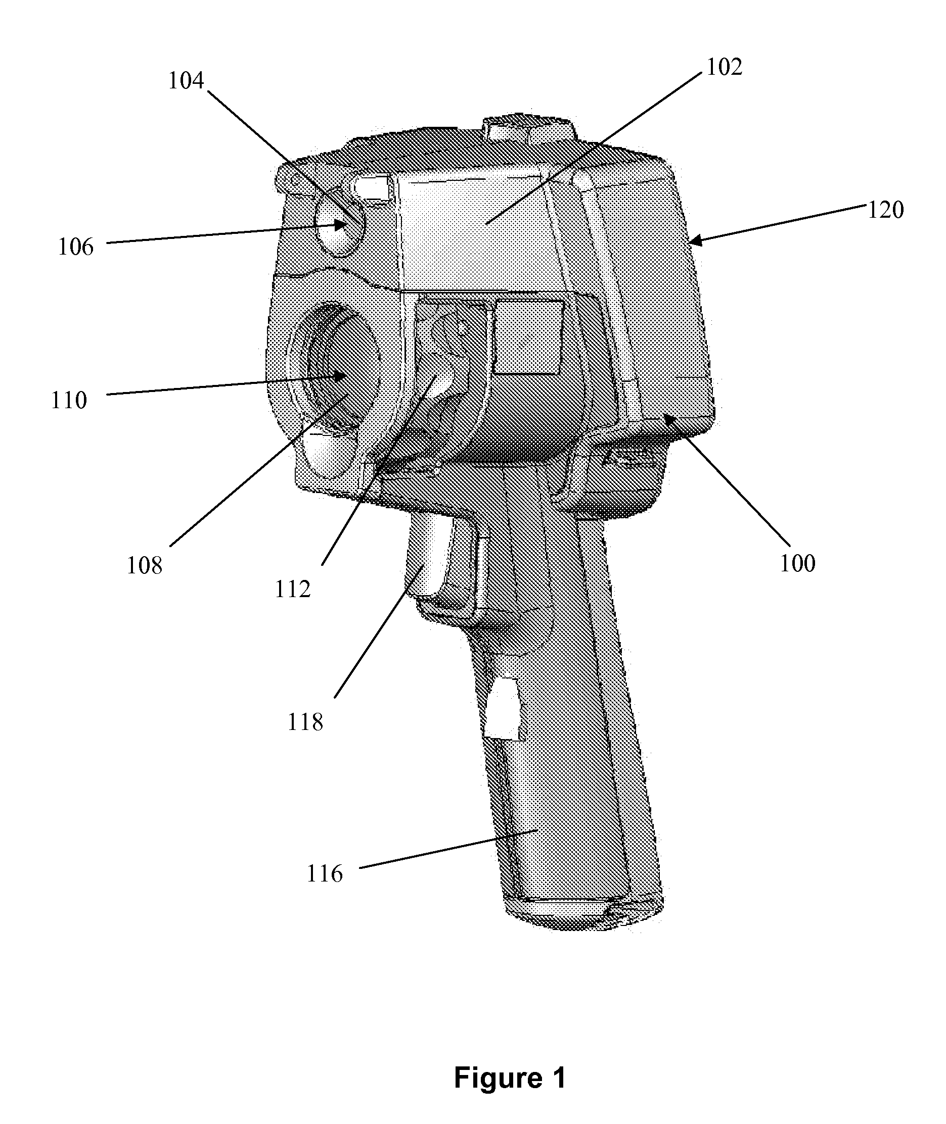
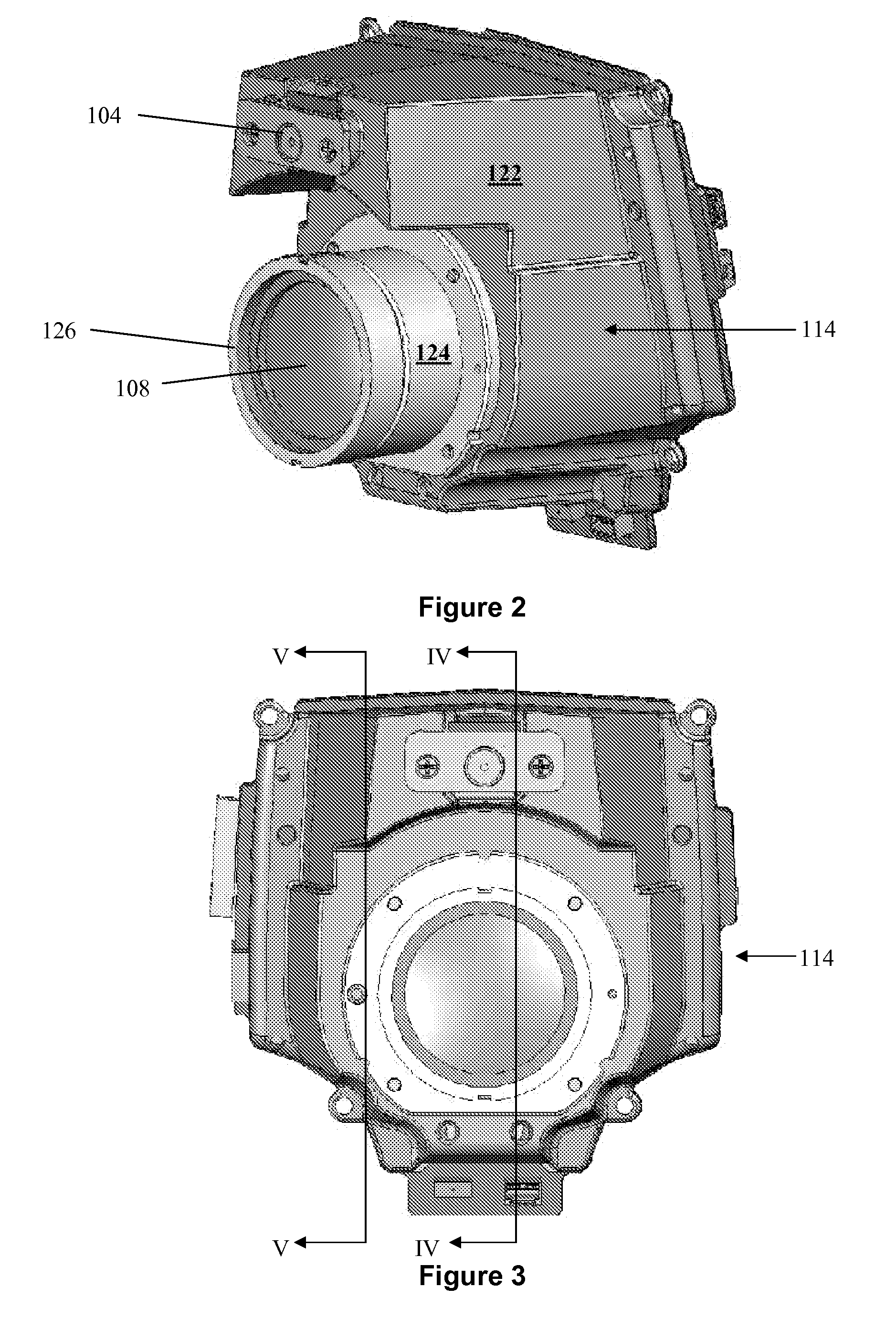
[0023]Embodiments of the present invention relate to an engine for a thermal instrument where the engine includes a thermal sensor that senses thermal or infrared radiation from a target scene. In some embodiments, the engine includes imaging capabilities, such as thermal imaging capabilities where the thermal sensor comprises an array of infrared detectors that sense a thermal image of the target scene. In some such engine embodiments, the thermal instrument includes a display for viewing the sensed thermal imagery. Moreover, in some such engine embodiments, the thermal instrument may include a storage mechanism such that the instrument functions as an infrared (IR) camera module that senses and sto...


PUM


Abstract

An engine for use in a thermal instrument. The engine includes an infrared camera module and may also include a visible light camera module. The engine includes several temperature sensors mounted on a printed circuit board assembly that permit the engine to provide improved radiometry functionality and improved fine offset compensation capabilities.

Description

TECHNICAL FIELD[0001]The present disclosure pertains to thermal instruments that sense thermal data of a target scene and more particularly to an engine of such a thermal instrument.BACKGROUND[0002]Handheld thermal imaging cameras, for example, including microbolometer detectors to generate infrared images, are used in a variety of applications, which include the inspection of buildings and industrial equipment. Many state-of-the-art thermal imaging cameras have a relatively large amount of built-in functionality allowing a user to select a display from among a host of display options, so that the user may maximize his ‘real time’, or on site, comprehension of the thermal information collected by the camera.[0003]As is known, infrared cameras generally employ a lens working with a corresponding infrared focal plane array (FPA) to provide an image of a view in a particular axis. The operation of such cameras is generally as follows. Infrared energy is accepted via infrared optics, in...

Claims


Application Information

Patent Timeline
Patent Type & Authority Patents(United States)
IPC IPC(8): G01J5/00
CPCG01J5/026G01J5/0265G01J5/027G01J5/028G01J5/0806G01J5/0834G01J5/12H04N5/2252H04N5/2253H04N5/33G01J2005/0077G01J2005/0081G01J5/0804G01J5/48H04N23/51H04N23/54
Inventor SHEARD, JUSTIN M.JOHNSON, KIRK R.LOUKUSA, MICHAEL E.JAMIESON, RICHARD M.
Owner JOHN FLUKE MFG CO INC
Why Eureka
Try Eureka