Exhaust system mixing device

a technology of mixing device and exhaust system, which is applied in the direction of mechanical equipment, machines/engines, transportation and packaging, etc., can solve the problems of reducing the effectiveness of catalyst, reducing the efficiency of catalyst, and creases in the fins, etc., and achieves easy manufacturing, improved flow mixing, and low cost

Inactive Publication Date: 2012-08-14
FORD GLOBAL TECH LLC
View PDF13 Cites 11 Cited by
  • Summary
  • Abstract
  • Description
  • Claims
  • Application Information

AI Technical Summary

Benefits of technology

[0005]The inventors of the present application have recognized a problem in such previous solutions. First, it may be difficult to manufacture such an apparatus since different fins must be bent at different angles in different directions. For example, as described above and shown in Brown's FIGS. 3-5, some fins are bent at obtuse angles whereas other adjacent fins are bent at reflex angles. Second, the creases where the fins are bent may be likely to collect urea. Such localized urea deposits may result in less of the urea being directed toward the catalyst, and thus reducing the effectiveness of the catalyst, and likewise, the SCR system.
[0007]In this way, by linking one fin section via its straight edge to another fin section via its curved edge, it is possible to create openings in the inner and outer regions of the mixing device that generate oppositely rotating flows of exhaust gas. As such, the mixing device enhances flow mixing downstream of the mixing device, while operating within the packaging constraints typical of an exhaust passage. Further, since each fin section may be identical, the fin sections may be easily manufactured, for example, via a stamping process. Thus, the fins may be manufactured at a low cost while still providing a robust mixing device. Moreover, the smooth surface of each fin section is free from creases, and thus, is not prone to urea buildup.

Problems solved by technology

First, it may be difficult to manufacture such an apparatus since different fins must be bent at different angles in different directions.
Second, the creases where the fins are bent may be likely to collect urea.
Such localized urea deposits may result in less of the urea being directed toward the catalyst, and thus reducing the effectiveness of the catalyst, and likewise, the SCR system.

Method used


Image

  • Exhaust system mixing device
  • Exhaust system mixing device
  • Exhaust system mixing device

Examples


Embodiment Construction

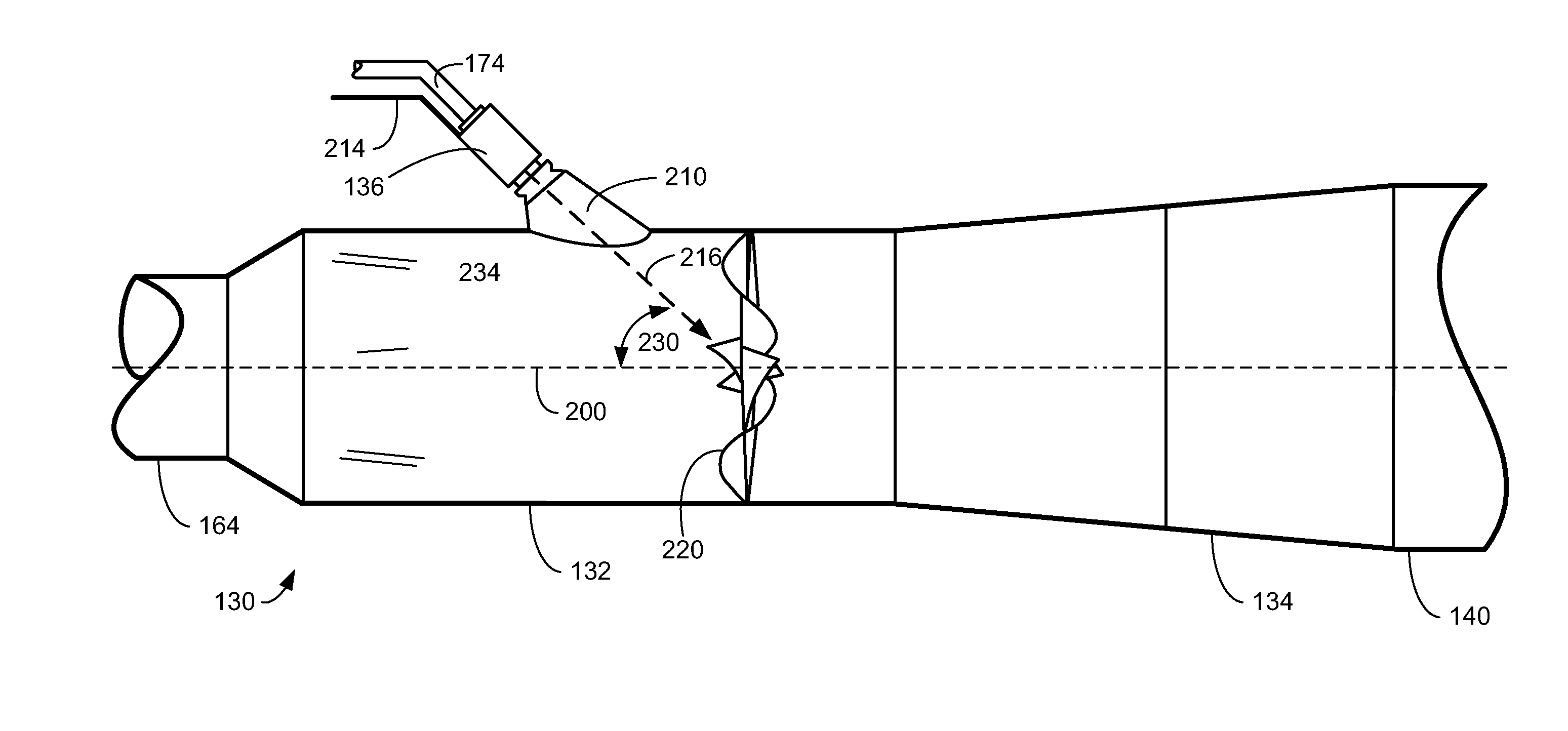
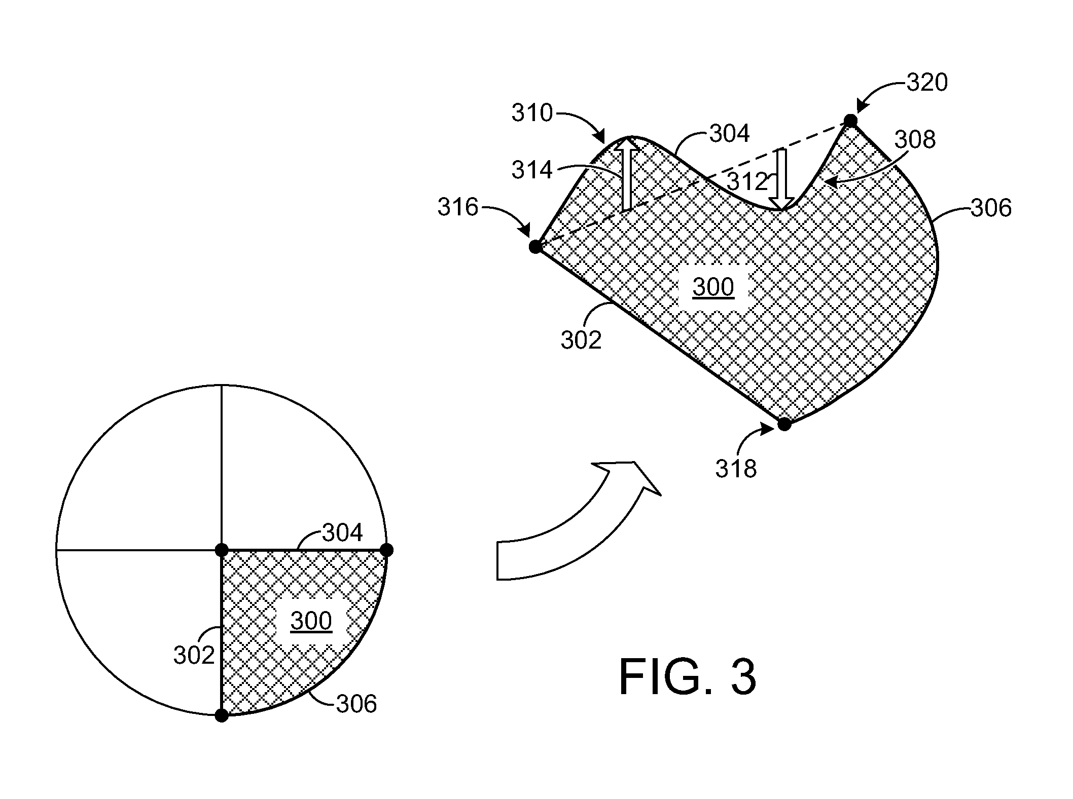
[0014]Embodiments of an exhaust system mixing device are disclosed herein. Such a mixing device may be utilized for creating two counter-rotated bulk flows forming a turbulent flow to enhance flow mixing, as described in more detail hereafter.

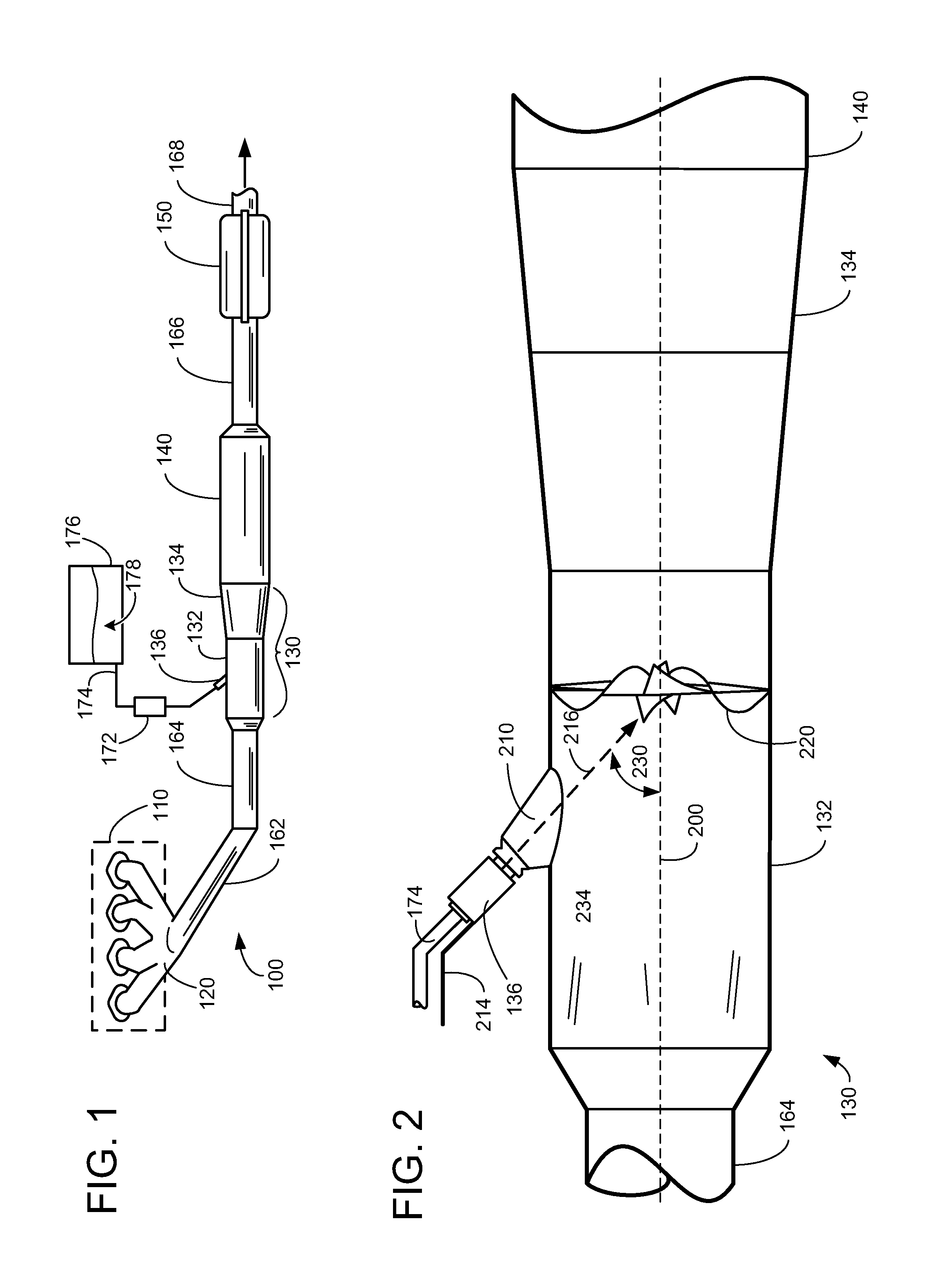
[0015]FIG. 1 illustrates an exhaust system 100 for transporting exhaust gases produced by internal combustion engine 110. As one non-limiting example, engine 110 includes a diesel engine that produces a mechanical output by combusting a mixture of air and diesel fuel. Alternatively, engine 110 may include other types of engines such as gasoline burning engines, among others.

[0016]Exhaust system 100 may include one or more of the following: an exhaust manifold 120 for receiving exhaust gases produced by one or more cylinders of engine 110, a mixing region 130 arranged downstream of exhaust manifold 120 for receiving a liquid reductant, a selective catalytic reductant (SCR) catalyst 140 arranged downstream of the mixing region 130, and a noise su...


PUM

PropertyMeasurementUnit
angleaaaaaaaaaa
angleaaaaaaaaaa
angleaaaaaaaaaa

Abstract

A mixing device comprises a circular disc of fin sections positioned so as to create openings in the inner and outer regions of the mixing device that generate oppositely rotating flows of exhaust gas. Each fin section may be identical, and may be created by a stamping process. The smooth surface of each fin section reduces creases, and thus, is less prone to urea buildup.

Description

TECHNICAL FIELD[0001]The present application relates to a mixing device for an exhaust system.BACKGROUND AND SUMMARY[0002]Many vehicles utilize catalysts in exhaust systems to reduce emission. In lean exhaust conditions, such as with regard to diesel exhaust or other lean burning conditions, catalyst may utilize reductant other than burnt fuel.[0003]One such aftertreatment device is a Selective Catalytic Reduction (SCR) system which uses a catalyst to convert NOx to nitrogen and water. A urea-based SCR catalyst may use gaseous ammonia as the active NOx reducing agent, in which case an aqueous solution of urea may be carried on board of a vehicle, and an injection system may be used to supply it into the exhaust gas stream. Further, a mixing device (e.g., a flow mixer) may be utilized to increase flow mixing within the distance / packaging constraints of the exhaust passage.[0004]In one mixing approach, namely U.S. Patent Application Publication No. 2008 / 0250776 (Brown, et al.), a mixi...

Claims


Application Information

Patent Timeline
Patent Type & Authority Patents(United States)
IPC IPC(8): F01N3/00
CPCB01F3/04049B01F5/0256B01F5/0473F01N3/2066F01N3/2892B01F5/0614Y02T10/24F01N2610/1453Y02T10/12B01F23/2132B01F2025/931B01F25/23B01F25/3141B01F25/4314
Inventor ZHANG, XIAOGANG
Owner FORD GLOBAL TECH LLC
Why Eureka
Try Eureka