Staple gun wire guide

a wire guide and stapling gun technology, applied in the field of stapling guns, can solve the problems of difficult operation, difficult dial operation, and difficulty in operation, and achieve the effect of convenient operation

Inactive Publication Date: 2012-08-14
ARROW FASTENER CO INC
View PDF18 Cites 17 Cited by
  • Summary
  • Abstract
  • Description
  • Claims
  • Application Information

AI Technical Summary

Benefits of technology

[0008]In an embodiment, a wire guide mechanism for a staple gun is disclosed which uses a minimal number of parts and is easily operated to extend and retract the wire guide element from the staple gun housing.
[0009]In at least one embodiment disclosed herein a staple gun tacker wire guide device of the character described is relatively simple in construction and reliable in use.
[0010]A staple gun tacker wire guide of the character described herein may require minimal modification of the staple gun and is inexpensive to manufacture.
[0012]The cam has a generally semi circular slot formed therein which has one end radially closer to the axis of rotation of the cam than its other end. The slot receives a protuberance or pin on the wire guide. When the cam is rotated the engagement of the protuberance or pin on the slot causes the wire guide to move linearly in the housing between extended and retracted positions. This structure provides a simple and easily operated wire guide feature in the staple gun.

Problems solved by technology

Previously proposed wire guide devices have been somewhat complicated to manufacture and cumbersome to use.
This requires a somewhat wider front housing than normal and the dial is difficult to operate.
This is difficult to do, particularly in work gloves.

Method used


Image

  • Staple gun wire guide
  • Staple gun wire guide
  • Staple gun wire guide

Examples


Embodiment Construction

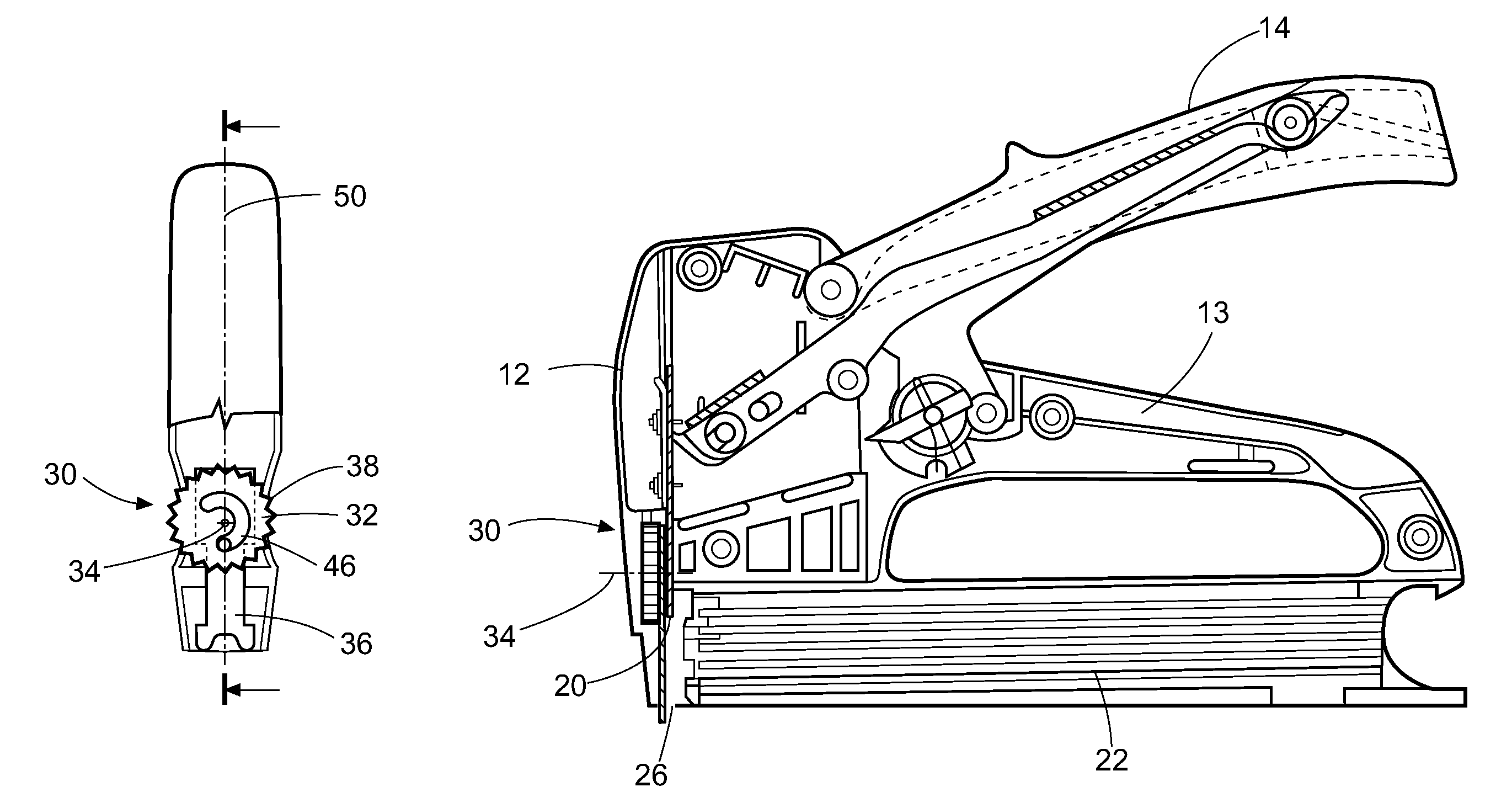
[0018]Unless stated otherwise, directions are used herein with reference to the normal orientation of the staple gun. Thus, the operating handle or lever is at the top of the device, and the direction toward the top is “up.” The staple driver is oriented vertically, located toward the “front” of the gun; staples come out of the “bottom” of the staple gun through a discharge opening, and the direction toward the bottom is “down.”

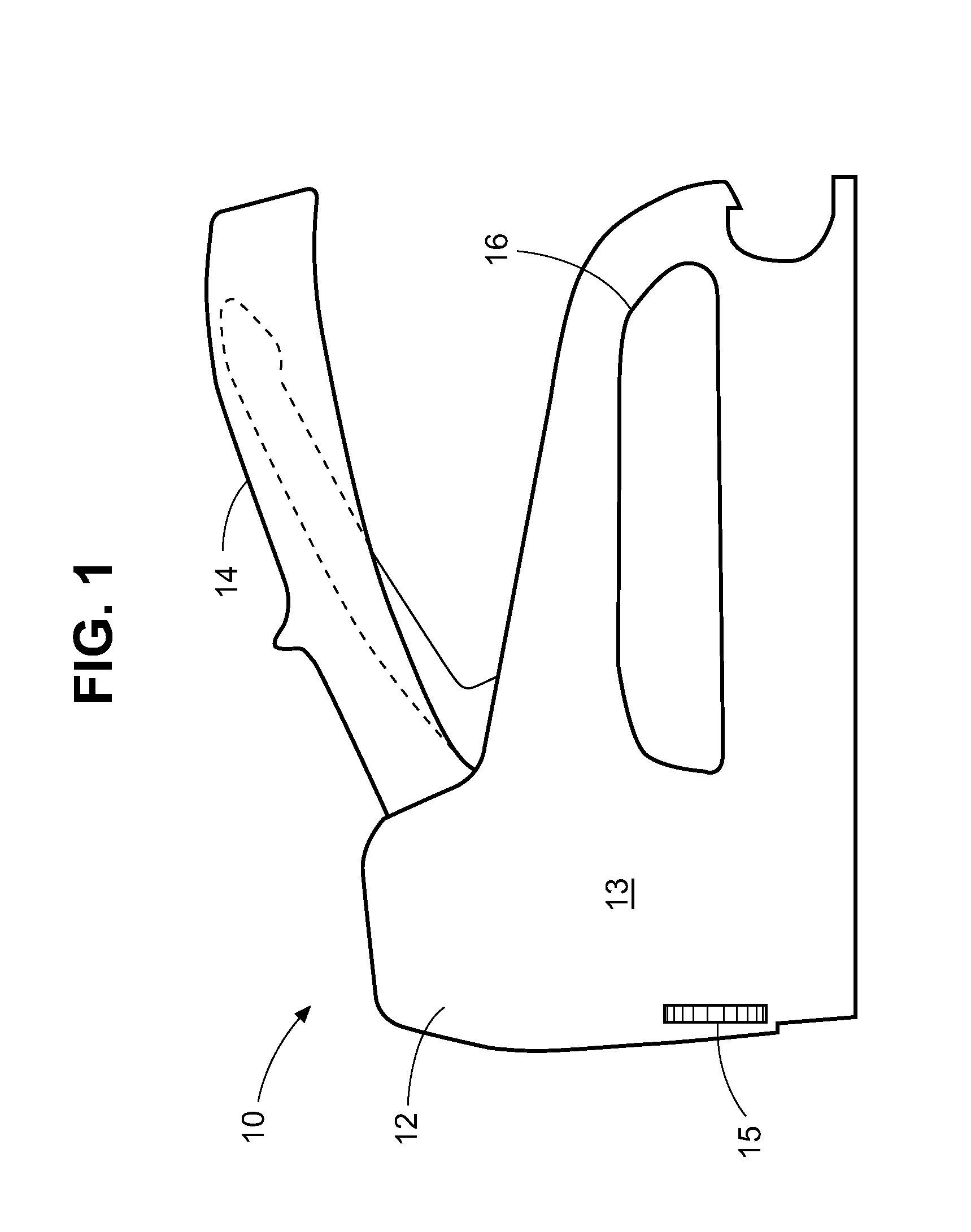
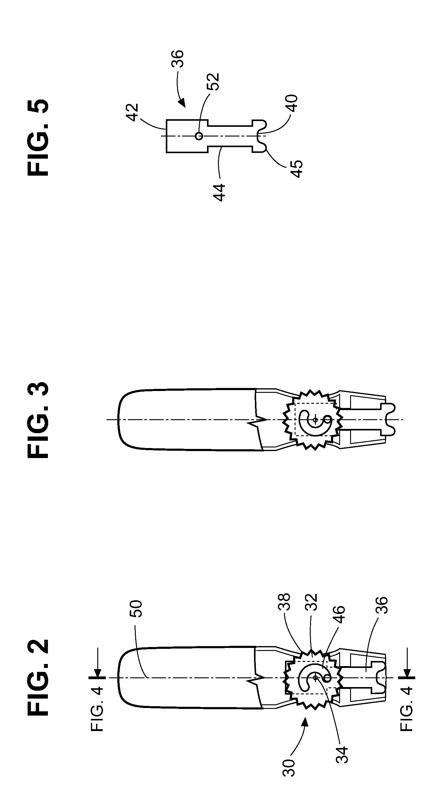
[0019]Referring now to the drawings in detail, and initially to FIG. 1, a staple gun tacker 10 of generally conventional and known construction is illustrated. The staple gun includes a housing 12, an operating lever or handle 14, and a finger hole opening 16. The interior of the housing contains an activating lever system 18 of known construction as illustrated in FIG. 4 which, when operated by the user depressing the handle 14, drives the staple driver or plate, sometimes referred to as the “knive,”20 downwardly to engage a staple in the staple supply track...


PUM


Abstract

A staple gun tacker includes a wire guide mechanism in its forward end which includes a wire guide plate having a recessed lower end for engaging a wire when the plate is in an extended position and a rotatable cam for moving the plate between extended and retracted positions which includes a circular slot formed therein having one end thereof located closer to the axis of rotation of the cam then the other receiving and engaged with a projection on the cam plate so that rotation of the cam is translated into linear movement of the wire guide plate.

Description

BACKGROUND[0001]1. Technical Field[0002]The multiple embodiments disclosed herein are directed towards the field of staple guns, and more particularly to a wire guide element for positioning the staple driving end of a staple gun tacker with respect to a wire or cable to be stapled to a workpiece.[0003]2. Description of Related Art[0004]Staple guns are well known hand-held tools adapted to drive staples into a workpiece. Arrow Fastener Co. manufactures and sells numerous models of such devices, including the manually operated non-powered staple gun sold under the T-50® brand name, and more recently powered models, such as the cordless CT-50™ staple gun.[0005]It is known to provide a wire guide for a staple gun, as disclosed for example in U.S. Pat. No. 5,884,829, and U.S. patent application Ser. No. 12 / 920,395, filed Aug. 31, 2010 both of which are assigned to the Arrow Fastener Co. and incorporated herein by reference. A wire guide is an element having a recessed surface that fits ...

Claims


Application Information

Patent Timeline
Patent Type & Authority Patents(United States)
IPC IPC(8): B25C5/02
CPCB25C5/06B25C5/0257
Inventor SHOR, ILYA
Owner ARROW FASTENER CO INC
Why Eureka
Try Eureka