High-pressure valve assembly

a valve assembly and high-pressure technology, applied in the direction of lift valves, water supply installation, functional valve types, etc., can solve the problems of reduced service life of the valve assembly and limited applicability of the valve assembly for very high pressur

Active Publication Date: 2012-08-14
HAMMELMANN MASCHFAB
View PDF7 Cites 34 Cited by
  • Summary
  • Abstract
  • Description
  • Claims
  • Application Information

AI Technical Summary

Benefits of technology

[0008]As in accordance with the present invention, the pressure-side tappet, when assuming the sealing position, projects into the chamber which has a bottom area in which the channel connects, an equilibrium of the hydrostatic pressure is established in radial direction when the tappet is moved axially in opposition to the spring force upon opening of the pressure valve, so that the presence of tensile stress in the outlet zone of the channel is avoided. As a result, there is no notch effect so that the stress on the valve body is minimized. The service life of the high-pressure valve assembly is thus increased and higher pressures can be absorbed so that the versatility of the valve assembly is significantly improved.
[0009]According to another advantageous feature of the present invention, the pressure chamber has a sidewall which may have at least one region to provide an axial guide surface for the tappet. As a result of the continuous support of the tappet in the valve body, the stress resistance of the high-pressure valve assembly is further enhanced.
[0015]According to another advantageous feature of the present invention, the valve body may have a bore for movably supporting and guiding the closure member. This design is beneficial as far as manufacture and operation are concerned.

Problems solved by technology

As a result, the service life of the valve assembly is reduced and the applicability of the valve assembly for very high pressures is limited.

Method used


Image

  • High-pressure valve assembly
  • High-pressure valve assembly
  • High-pressure valve assembly

Examples


first embodiment

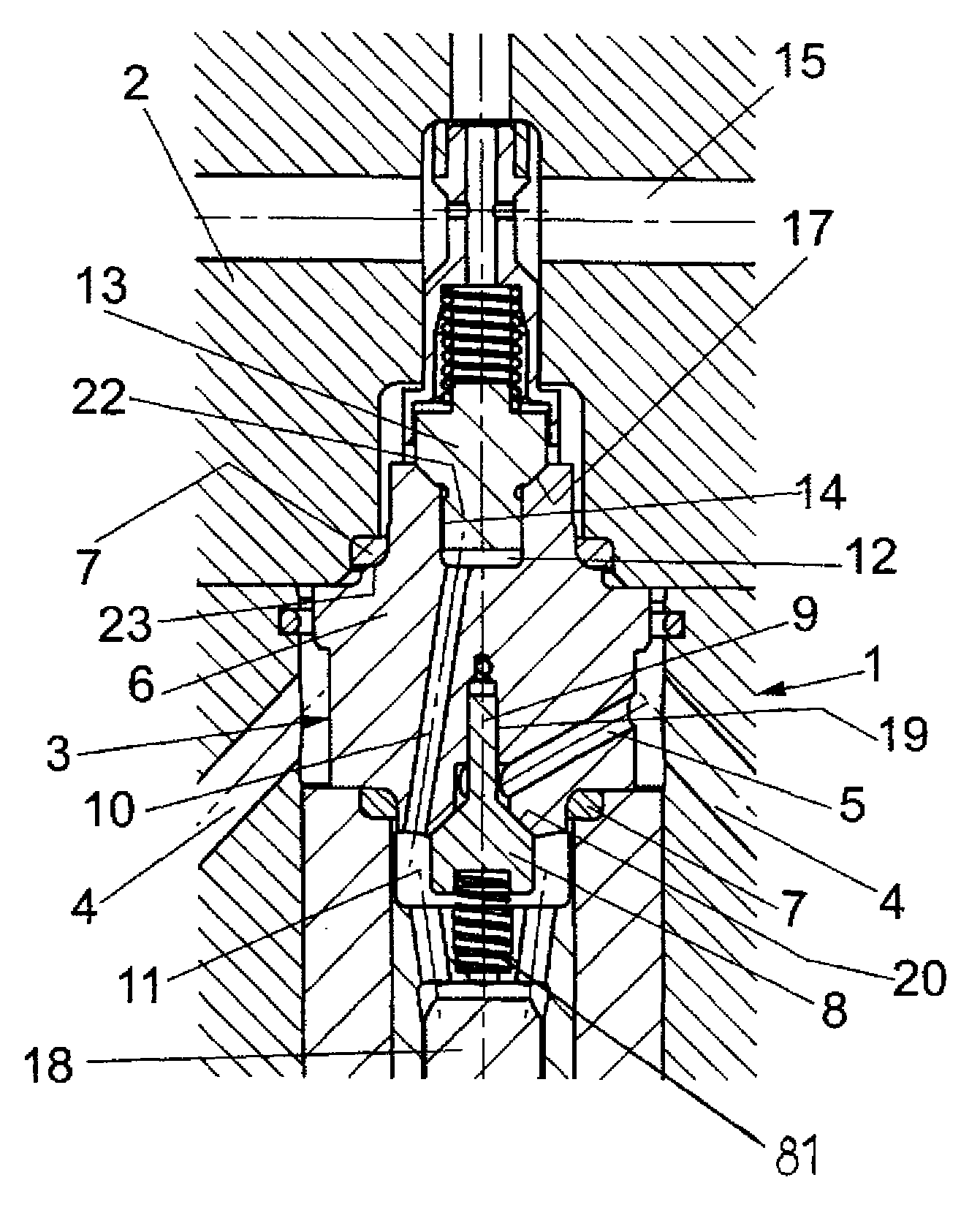
[0022]Turning now to the drawing, and in particular to FIG. 1, there is shown a sectional side view of a high-pressure valve assembly according to the present invention, generally designated by reference numeral 3 and including a valve body 6 which has a suction side supported in a housing 1 and a pressure side supported in a flange 2 which is connected to the housing 1. Static ring seals 7 are provided to seal the valve body 6 against the housing 1 and the flange 2, respectively.

[0023]The housing 1 is provided with inlet bores 4 for routing a fluid into a suction space 11 via a suction line 5 arranged in the valve body 6. The supply of fluid is controlled by a closure member 8 which is urged by spring 81 to rest snugly against the valve body 6 in order to close the suction line 5. The closure member 8 is formed with a pin 9 which extends axially for movement in a bore 19 of the valve body 6. The bore 19 thus forms a guidance for the pin 9 and hence also for the closure member 8.

[00...

second embodiment

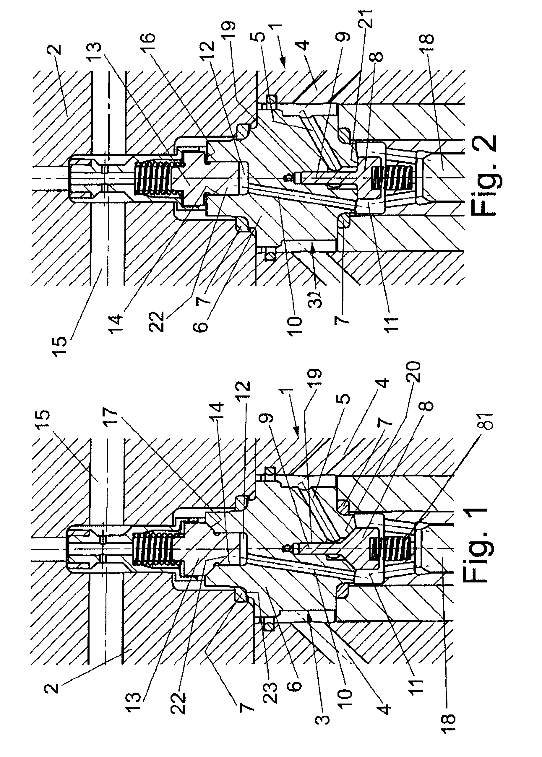
[0026]FIG. 2 shows a sectional side view of a high-pressure valve assembly according to the present invention, generally designated by reference numeral 32. Parts corresponding with those in FIG. 1 are denoted by identical reference numerals and not explained again. The description below will center on the differences between the embodiments. In this embodiment, the tappet 13 has a circumferential shoulder, which forms a sealing surface 16 for cooperation with a complementary sealing surface of the valve body 6. Both the sealing surface 16 of the tappet 13 and the associated sealing surface of the valve body 6 have a flat or planar configuration, i.e. perpendicular to the length axis of the tappet 13. The closure member 8 has also a sealing surface 21 which snugly rests upon a complementary sealing surface of the valve body 6.

third embodiment

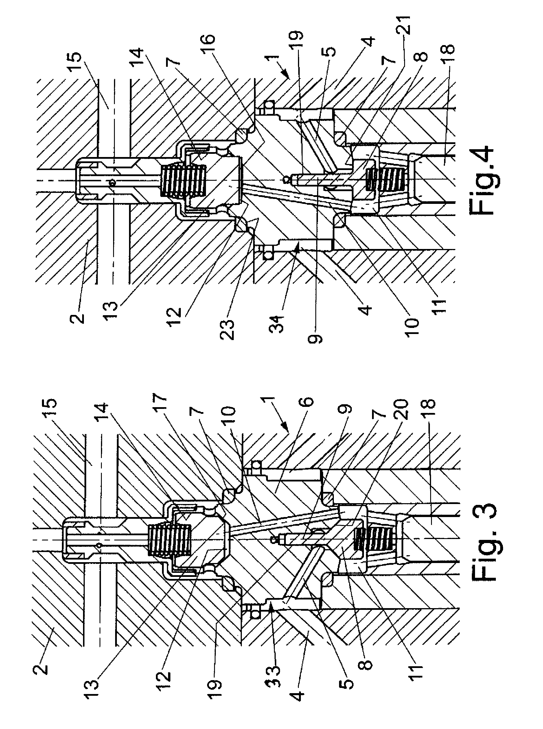
[0027]FIG. 3 shows a sectional side view of a high-pressure valve assembly according to the present invention, generally designated by reference numeral 33. Parts corresponding with those in FIGS. 1 and 2 are denoted by identical reference numerals and not explained again. The description below will center on the differences between the embodiments. In this embodiment, the tappet 13 has an end surface which together with the complementing surface of the pressure chamber 12 serves as sealing surface 17 for sealing the channel 10 which ends in the bottom region of the pressure chamber 12. The sealing surface 17 has a conical configuration formed with a bevel. The pressure chamber 12 conforms hereby in the contact zone to the sealing surface 17.


PUM


Abstract

A high-pressure valve assembly includes a flange defining an axis. Projecting into the flange is a valve body which is sealed against the flange by a static ring seal. Provided on one side of the valve body is a spring-loaded closure member which is supported for movement in a direction of the axis to form a suction valve, and on another side of the valve body in opposition to the one side is a spring-loaded tappet which is supported for movement in the direction of the axis to form a pressure valve. A channel connects the suction valve with the pressure valve and has one end porting into a pressure chamber of the valve body adjacent to the pressure valve. The pressure chamber extends in axial direction of the tappet and is sized to extend substantially above a bottom edge of the ring seal.

Description

CROSS-REFERENCES TO RELATED APPLICATIONS[0001]This application claims the priority of German Patent Application, Serial No. 20 2008 001 458.1, filed Feb. 1, 2008, pursuant to 35 U.S.C. 119(a)-(d), the content of which is incorporated herein by reference in its entirety as if fully set forth herein.BACKGROUND OF THE INVENTION[0002]The present invention relates to a high-pressure valve assembly.[0003]Nothing in the following discussion of the state of the art is to be construed as an admission of prior art.[0004]High-pressure valve assemblies are used in high-pressure pumps by which a fluid is pressurized to a pressure of, for example, 4000 bar and above. The valve assembly has a pressure valve having a spring-loaded tappet which is movable in an axial direction and has an end surface to form a sealing surface resting against a complementary end surface of a valve body, when assuming a sealing position, so as to snugly seal a channel during a suction step. The suction valve includes a...

Claims


Application Information

Patent Timeline
Patent Type & Authority Patents(United States)
IPC IPC(8): F16K31/12
CPCF04B1/0452F04B53/1022F04B53/109Y10T137/88062
Inventor JARCHAU, MICHAELSOMMERKAMP, AXEL
Owner HAMMELMANN MASCHFAB
Why Eureka
Try Eureka