Seal structure

a technology of sealing structure and film, applied in the direction of mechanical equipment, machines/engines, coatings, etc., can solve the problems of limited sealing performance and difficulty in forming a sufficient thickness of film, and achieve the effects of improving reliability, improving sealing performance, and improving the performance of rotary machines

Active Publication Date: 2012-08-14
MITSUBISHI POWER LTD
View PDF22 Cites 9 Cited by
  • Summary
  • Abstract
  • Description
  • Claims
  • Application Information

AI Technical Summary

Benefits of technology

[0008]As described above, by applying an abradable material, the advantages in terms of a clearance design are great, and there are various known materials which can be used as the abradable material. Regarding a ring-shaped member, such as a turbine member, on which a uniform film thickness is required, for example, a coating (a film) of the abradable material obtained by inner diameter thermal spraying is believed to be effective. With the thermal spraying processing, since semi-solid particles being thermally sprayed shrink upon solidification after adhering to a base material (the opposing surface of the fins), residual stress is developed thereby. The thicker the film becomes, the greater the residual stress will be. As this residual stress is increased, the film will separate at the interface between the base material and the film (interfacial separation will occur). This becomes prominent particularly when the abradable material is applied to a curved surface, such as the ring member of a turbine. Furthermore, the effect tends to be greater at the edges of the film.

Problems solved by technology

In practice, therefore, it is difficult to form a film having a sufficient thickness.
Thus, with significant concern for safety, the clearance in the rated rotational speed range has to be widened, and the sealing performance has to be limited under the current situation.

Method used


Image

  • Seal structure
  • Seal structure
  • Seal structure

Examples


Embodiment Construction

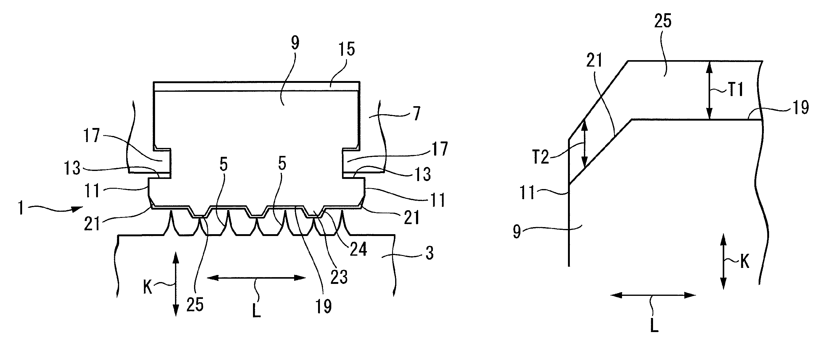
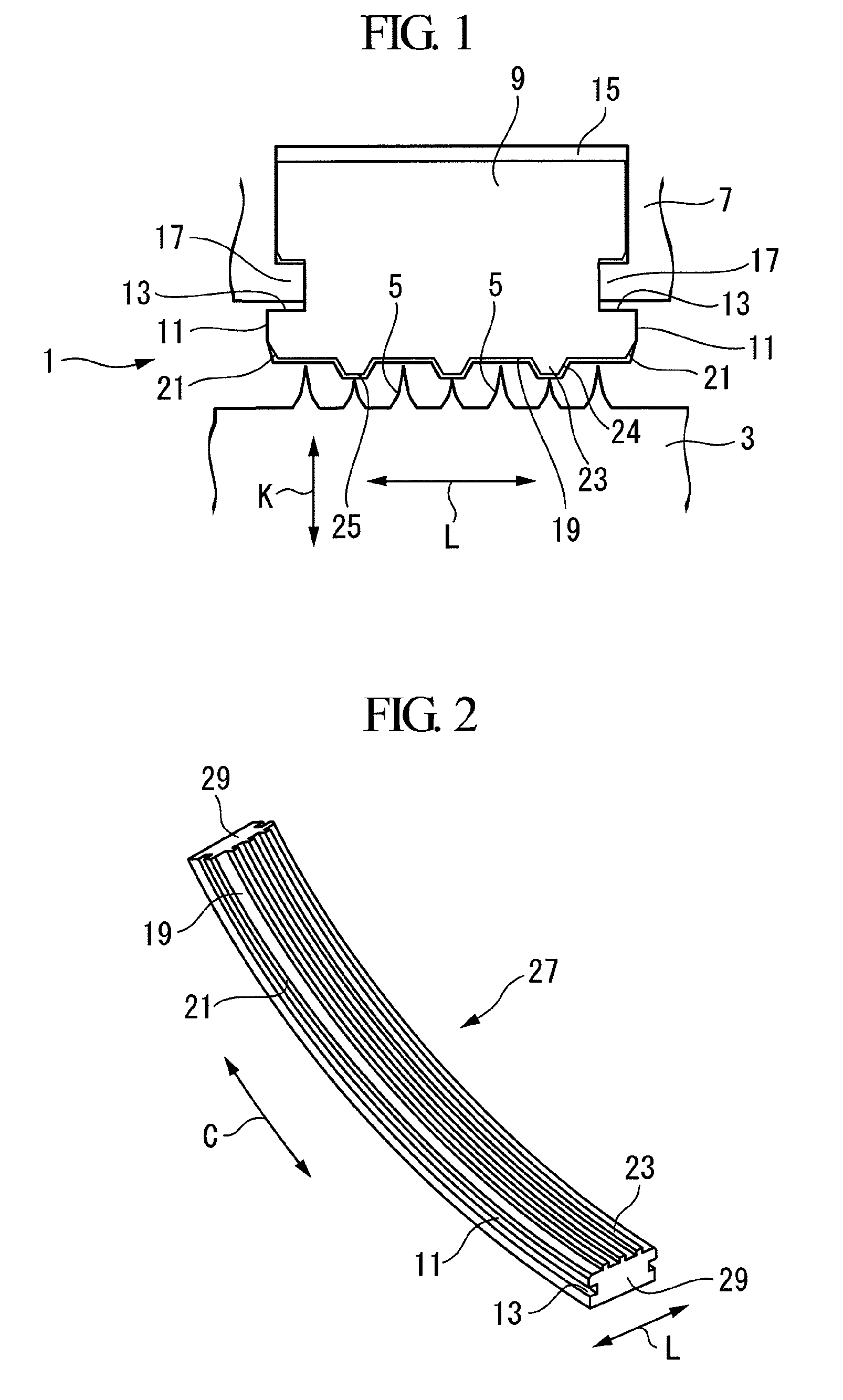
[0069]In the following, a seal structure 1 used in a rotating shaft part of a rotary machine, such as a steam turbine, a gas turbine, a compressor, etc., according to an embodiment of the present invention will be described below with reference to FIGS. 1 to 7.

[0070]FIG. 1 is a longitudinal sectional view of a seal structure 1 according to this embodiment.

[0071]The seal structure 1 is provided with a plurality of fins 5 projected in a ring-shape from a circumferential surface of a rotating shaft (rotating member) 3 and a doughnut-shaped seal member 9 that is, for example, held on a stationary part 7, such as a housing etc., so as to cover the outer circumferential side of the fins 5.

[0072]The plurality of fins 5 are arranged with gaps therebetween along the axial direction L. The fins 5 are integrally formed with the rotating shaft 3 by milling.

[0073]The fins 5 may be separately formed from the rotating shaft 3 and then fixed on the rotating shaft 3 by means such as embedding etc.

[0...


PUM

PropertyMeasurementUnit
thickaaaaaaaaaa
thicknessaaaaaaaaaa
temperatureaaaaaaaaaa

Abstract

A seal structure includes a thick abradable film, thereby improving sealing performance. A seal structure (1) is provided with at least one fin (5) that projects in a ring-shape from a circumferential surface of a rotating shaft (3) and that is provided along an axial direction (L) and a seal member (9) having a ring-shaped sealing surface (19) opposed to the fin (5), and on which an abradable layer (25) is formed by thermally spraying abradable material onto the sealing surface (19), the seal structure (1) is provided with tapered portions (21) inclined in a radial direction (K) at end portions of the sealing surface (19) in the axial direction (L).

Description

TECHNICAL FIELD[0001]The present invention relates to a seal structure that is used for a rotating shaft part of a rotary machine.BACKGROUND ART[0002]As a seal structure of a rotating shaft part in a rotary machine, such as a steam turbine, a gas turbine, a compressor, etc., a so-called labyrinth seal structure, such as those mentioned in, for example, Patent Citation 1 and Patent Citation 2, is widely used.[0003]The labyrinth seal structure is formed of a plurality of fins that project in a ring-shape and that are provided along the axial direction on a rotating shaft or a stationary part opposed thereto and a surface opposed to these fins (opposing surface). Even though the fins are machined to have sharp tips of about 0.2 mm in order to reduce the influence of contact with the opposing surface, since it essentially involves contact between metals, the amount of heat generated by the sliding is great, and a shaft vibration may be caused during heavy contact; therefore, the clearan...

Claims


Application Information

Patent Timeline
Patent Type & Authority Patents(United States)
IPC IPC(8): F16J15/447
CPCC23C4/06F01D11/001F01D11/02F16J15/445F16J15/453F05D2250/314F05D2230/90
Inventor HIRAKAWA, YUICHIUEHARA, HIDEKAZUNAKANO, TAKASHINISHIMOTO, SHIN
Owner MITSUBISHI POWER LTD
Why Eureka
Try Eureka