
Flashing material

a technology of flashing material and sealing strip, which is applied in the direction of walls, synthetic resin layered products, transportation and packaging, etc., can solve the problems of sealing strip becoming “unstuck”, self-adhesion membranes, and joints within component elements providing leakage paths

Active Publication Date: 2012-08-14
DRYVIT SYST
View PDF11 Cites 0 Cited by
  • Summary
  • Abstract
  • Description
  • Claims
  • Application Information

AI Technical Summary

Benefits of technology

[0002]Exterior closures, such as doors and windows, must generally provide a barrier between the outside and the inside of the structure in which they are used. Accordingly, rough openings in exterior walls are often sealed using sheet products in the form of felt, fiber reinforced felt papers, house wrap products, and polyethylene backed self-adhering membranes. This is intended to prevent water which may enter from inadvertent leakage, from coming into direct contact with moisture sensitive materials such as framing and sheathing.
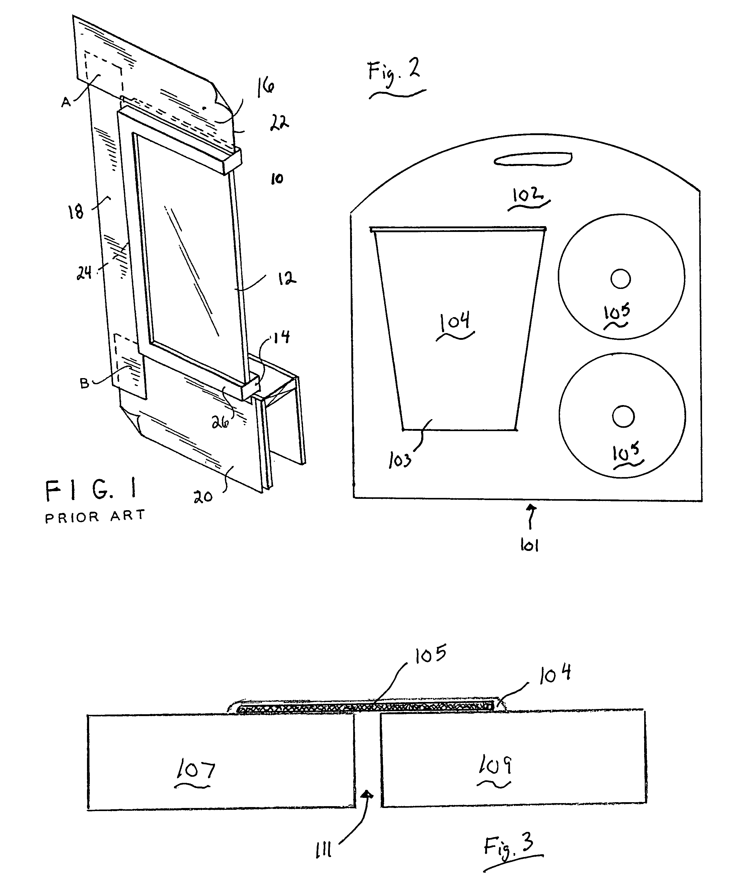
[0004]In FIG. 1, a typical nail-on window frame assembly 6 is shown. The assembly 10 includes a glass pane 12 set in a frame 14. Flashing materials 16, 18 and 20 overlap the nailing flanges on the respective head 22, jamb 24 sides of the frame 14 and under the sill flange 26. The flashing materials 16, 18 and 20 are typically of polymeric material or the like of low permeance, exhibiting negligible moisture vapour penetration. The flashing materials 16, 18 and 20 are applied sequentially as sealing strips resulting in overlap at regions A, B and so on at each of the corners. An exemplary sealing strip comprises a polymeric sheet which is usually stapled to the sheathing. The stapling can provide minor leakage paths. Necessarily, the sealing strips are applied in a sequence resulting in lapping wherein an upper layer is applied over a lower layer to properly shed water.

Problems solved by technology

Moreover, it has been found that joints within component elements can provide leakage paths.
Unfortunately, self-adhering membranes, such as those of either a rubberized asphalt or butyl adhesive backed polyethylene sheet exhibit poor adhesion on selected substrates in selected conditions.
Therefore, depending on when the cladding crew can be scheduled and how long it takes to prepare and apply the particular exterior system used, the sealing strips may become “unstuck”, or they can wrinkle, and otherwise can provide a less than perfect seal.

Method used


Image

  • Flashing material
  • Flashing material

Examples


Embodiment Construction

[0013]Referring now to FIG. 2, the present invention comprises a kit 101 having a housing 102 including a bucket 103 containing a sizing composition 104 and two mesh 105 rolls. The housing can be comprised of any typical packaging materials including polymeric or paper products. The sizing comprises a waterproof, water-based polymer material used in conjunction with the mesh to seal joints around window, door and other openings. The invention provides an effective water and weather resistive membrane for covering joints around window, door and other structures.

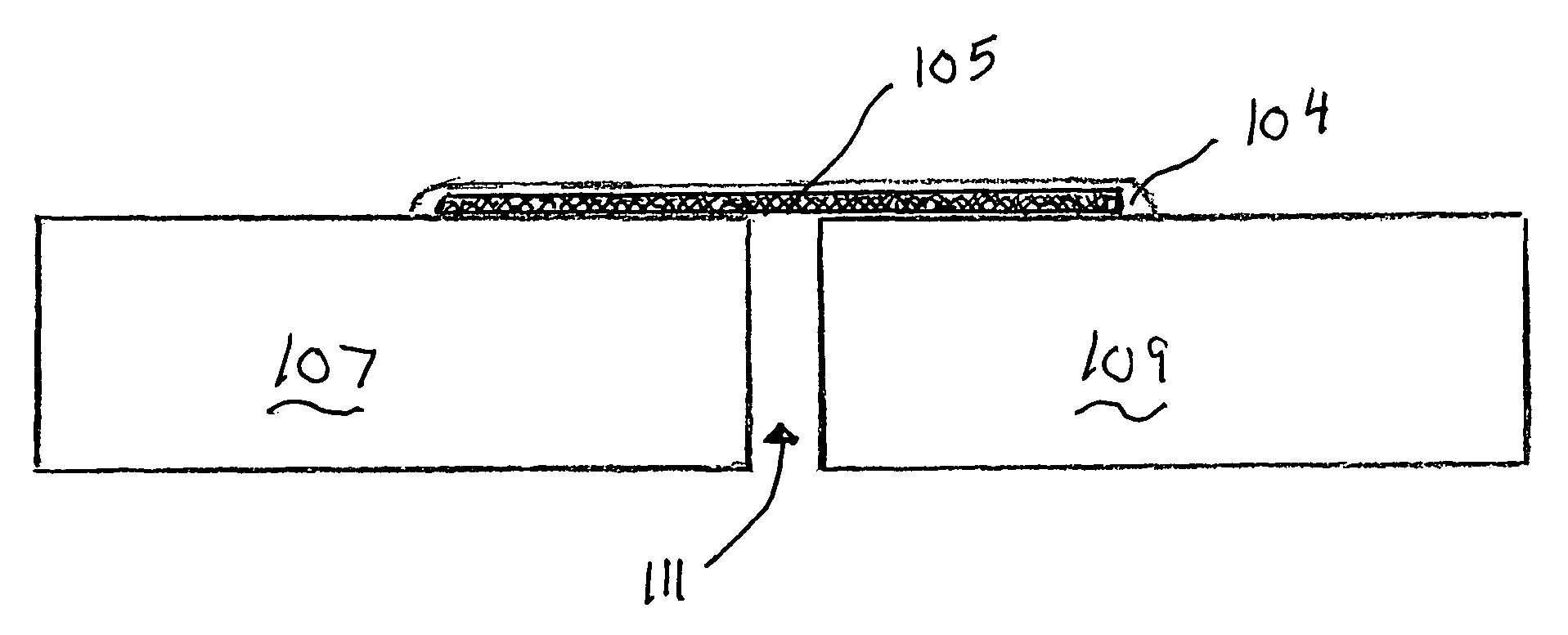
[0014]Referring now to FIG. 3, the present seal is illustrated as affixed to structural elements 107 and 109. The mesh 105, which is embedded in sizing 103 forms an effective seal over gap 111. The mesh 105 is preferably porous such that it can sufficiently embed and absorb sizing 104. A preferred mesh is comprised of a porous non-woven closed weave material. However, the skilled artisan will recognize that an open weave mater...


PUM

PropertyMeasurementUnit
specific gravityaaaaaaaaaa
lengthaaaaaaaaaa

Abstract

A method of sealing a construction joint is provided which comprises applying a polymeric sizing to the edges forming the joint, applying a mesh to the joint and applying a further coating of the sizing to said deposited mesh. The sizing material can comprise a styrene-butadiene latex, a filler and at least one of a colorant, an acrylic thickener, dispersant, biocide, defoamer, antifoamer, surfactant and an acid.

Description

[0001]The present invention relates generally to a system for sealing construction joints. More particularly, the system relates to sealing joints around, for example, windows and doors during the construction of a structure and comprises the components of the system and a method for sealing joints using the system.[0002]Exterior closures, such as doors and windows, must generally provide a barrier between the outside and the inside of the structure in which they are used. Accordingly, rough openings in exterior walls are often sealed using sheet products in the form of felt, fiber reinforced felt papers, house wrap products, and polyethylene backed self-adhering membranes. This is intended to prevent water which may enter from inadvertent leakage, from coming into direct contact with moisture sensitive materials such as framing and sheathing.[0003]Moreover, it has been found that joints within component elements can provide leakage paths. Even where these joints are tightly glued a...

Claims


Application Information

Patent Timeline
Patent Type & Authority Patents(United States)
IPC IPC(8): B32B37/15
CPCE06B1/62E06B2001/622E06B2001/628
Inventor LAFEVRE, RICHARDPATIL, CHANDER
Owner DRYVIT SYST
Learn More