Rotor disk for turbomachine fan

a technology of rotor disk and turbomachine, which is applied in the direction of liquid fuel engines, marine propulsion, vessel construction, etc., can solve the problems of limiting the stress applied to the disk and the inter-vane platform, and achieve the effect of avoiding serious damage to the turbomachine and limiting the stress

Active Publication Date: 2012-08-21
SN DETUDE & DE CONSTR DE MOTEURS DAVIATION S N E C M A
View PDF15 Cites 4 Cited by
  • Summary
  • Abstract
  • Description
  • Claims
  • Application Information

AI Technical Summary

Benefits of technology

[0008]In the event of loss of a vane, the stresses exerted by the vane roots on the disk are greatest at the downstream end of the disk and cause local plastic deformation of the cavities of the attachment flanges of the inter-vane platforms, which limits the stress applied to the disk and to the inter-vane platforms. The vanes and platforms can thus be retained in position until the engine is brought to a stop, thus avoiding serious damage to the turbomachine.
[0009]The vanes of the rotor disk according to the invention no longer require axial machining to divert the forces. This eliminates the phenomena of disk and vane wear due to this machining while also limiting the stresses applied to the hooks and transmitted to the platforms, because of the cavities formed in the attachment flanges of the inter-vane platforms.

Problems solved by technology

In the event of loss of a vane, the stresses exerted by the vane roots on the disk are greatest at the downstream end of the disk and cause local plastic deformation of the cavities of the attachment flanges of the inter-vane platforms, which limits the stress applied to the disk and to the inter-vane platforms.

Method used


Image

  • Rotor disk for turbomachine fan
  • Rotor disk for turbomachine fan
  • Rotor disk for turbomachine fan

Examples


Embodiment Construction

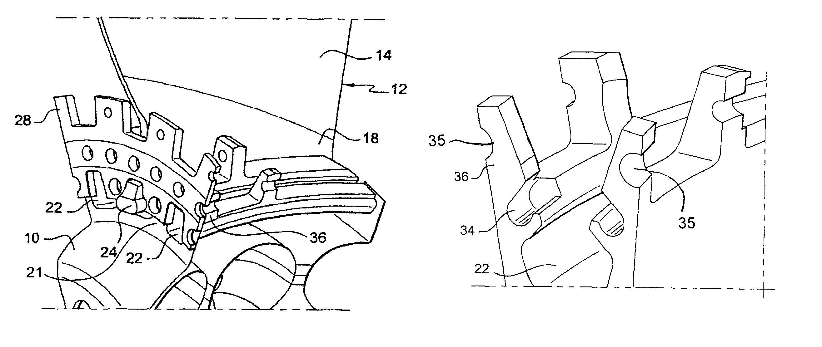
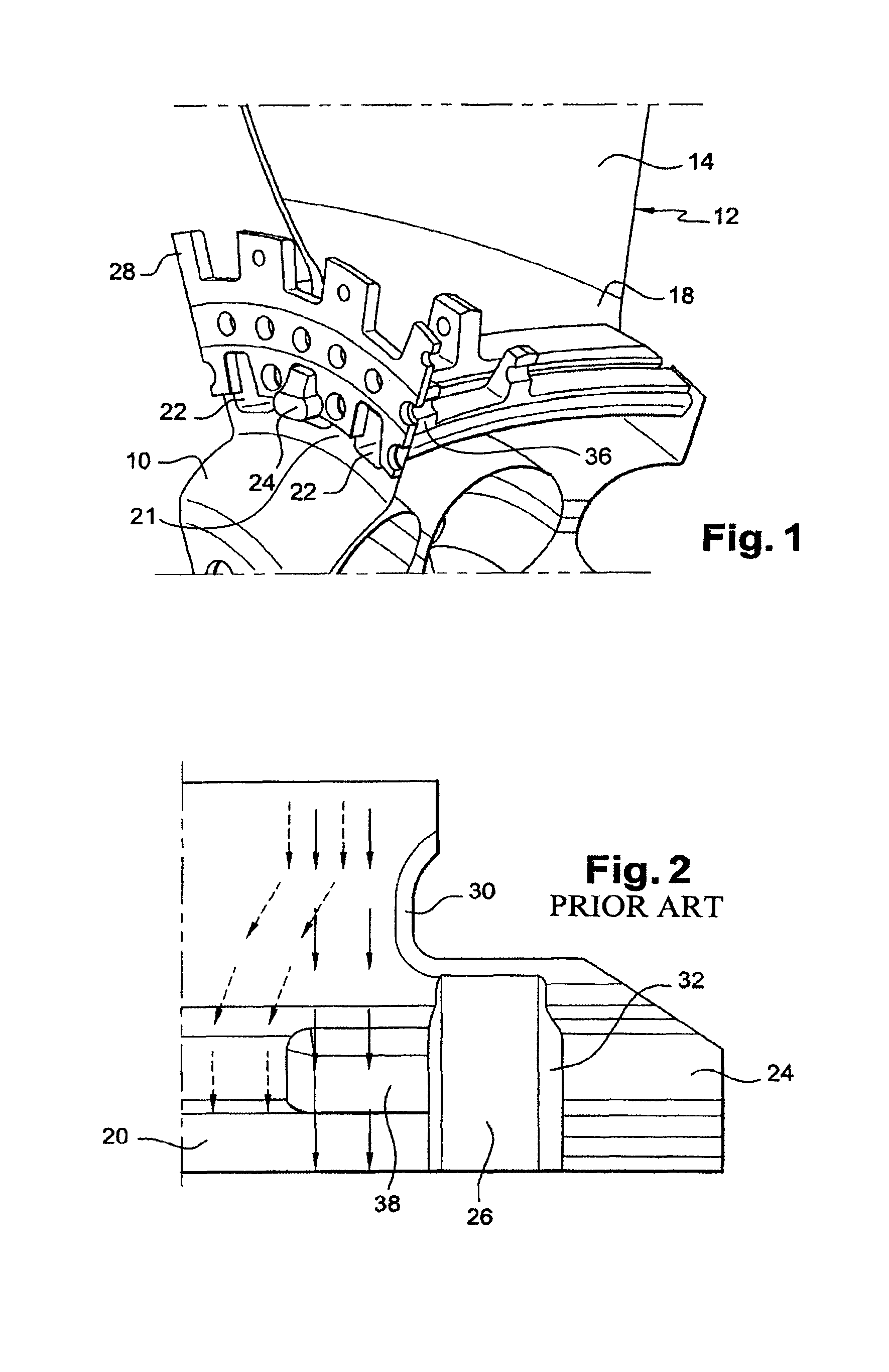
[0021]Referring initially to FIG. 1, this shows a fan disk 10 carrying a vane 12, while FIG. 2 shows the radially inward downstream part of a prior-art vane.

[0022]A vane is made up of a blade 14 connected to a vane root 20 via an intermediate section 18. The disk 10 comprises a plurality of essentially alternating axial ribs 21 and grooves 22 distributed regularly around its outer perimeter, the vanes 12 being engaged in the grooves 22. Platforms (not shown) are arranged between the vanes and serve to orient the airstream entering the turbomachine. The vane root 20, of dovetail or similar shape, engages with the groove 22 for the radial retention of the vane (12) on the rotor disk 10. In the downstream continuation of the vane root 20 of the disk 10 there is formed a hook 24 comprising a radial recess 26 on each of its lateral faces. These recesses engage with an annular plate 28 to lock the root 20 of the vane 12 axially in the groove 22 of the disk 10.

[0023]When the turbomachine i...


PUM


Abstract

A rotor disk for a fan in a turbomachine is disclosed. The disk includes in its perimeter a plurality of essentially axial grooves for the installation and retention of vane roots having hooks at their downstream ends, and deformable regions formed by cavities being situated at the downstream end of the grooves in attachment flanges for inter-vane platforms to absorb the stresses between the disk and the vane roots.

Description

[0001]This invention relates to a rotor disk for a turbomachine fan, such as in an aircraft turbojet in particular.BACKGROUND OF THE INVENTION[0002]In the prior art, a fan rotor disk comprises a plurality of vanes mounted around its perimeter and separated from each other by platforms fixed to disk flanges. Each vane is made up of a blade connected to a vane root by an intermediate section. The vane roots are engaged in grooves formed essentially axially in the perimeter of the disk and are held in these radially by the interlocking of their shapes, the vane roots being for example dovetailed or the like in transverse section.[0003]When the turbomachine is operating, loss of the connection of a vane to the disk can result in the destruction of the neighboring vanes and associated platforms. What happens is that if a fan vane is lost, it pushes against the neighboring vane, and the resulting force applied to this vane causes in particular an axial stress directed in the upstream dire...

Claims


Application Information

Patent Timeline
Patent Type & Authority Patents(United States)
IPC IPC(8): B64C11/04
CPCF01D5/3007F01D21/045F04D29/322
Inventor LE HONG, SON
Owner SN DETUDE & DE CONSTR DE MOTEURS DAVIATION S N E C M A
Why Eureka
Try Eureka