Calibration method for ring artifact correction in non-ideal isocentric 3D rotational X-ray scanner systems using a calibration phantom based rotation center finding algorithm

a technology of phantom based rotation center finding and calibration method, which is applied in the field of 3d rotational xray imaging systems, can solve the problem that the ct scan cannot be performed over an angular range of 180°

Inactive Publication Date: 2012-08-21
KONINK PHILIPS ELECTRONICS NV
View PDF19 Cites 7 Cited by
  • Summary
  • Abstract
  • Description
  • Claims
  • Application Information

AI Technical Summary

Benefits of technology

[0013]The present invention is thus addressed to the object of facilitating the correction of scanner-based circular ring artifacts which may arise when using a not perfectly isocentric 3D rotational X-ray scanner system due to non-isocentric motion of the X-ray tube and detector array, thus improving the image quality of tomographically reconstructed 3D images which are calculated based on a set of voxel data obtained by combining the image data of a set of 2D projection images which are acquired from a number of distinct projection directions along a substantially circular trajectory around an object of interest to be visualized.
[0014]In view of this object, a first exemplary embodiment of the present invention refers to a calibration method for eliminating substantially circular ring artifacts in a set of radiographic 2D projection images which are acquired from a number of distinct projection directions by a not perfectly isocentric 3D rotational X-ray scanner system equipped with at least one X-ray tube and at least one associated X-ray detector diametrically arranged with respect to said X-ray tube.
[0019]A second exemplary embodiment of the present invention is directed to a method for tomographically reconstructing an object of interest from a set of radiographic 2D projection images acquired from a number of distinct projection directions by a not perfectly isocentric 3D rotational X-ray scanner system which comprises at least one X-ray tube and at least one associated X-ray detector diametrically arranged with respect to said X-ray tube, wherein said images are acquired when moving said X-ray tube and said X-ray detector along two circular trajectories around said object. According to the present invention, said method may include a calibration method for eliminating substantially circular ring artifacts as set forth above with respect to said first exemplary embodiment.

Problems solved by technology

These methods imply the disadvantages that they provide “a solution” but not necessarily the best, that they do not work for CT scans spanning an angular range of 180° or less (such as e.g. for XperCT roll scans, which are part of Philips' XtraVision product) and that the they do not account for the axis of rotation not being perfectly perpendicular to the image acquisition plane of the substantially circular trajectories along which the X-ray tube and detector array are moved when acquiring a set of 2D projection images.

Method used


Image

  • Calibration method for ring artifact correction in non-ideal isocentric 3D rotational X-ray scanner systems using a calibration phantom based rotation center finding algorithm
  • Calibration method for ring artifact correction in non-ideal isocentric 3D rotational X-ray scanner systems using a calibration phantom based rotation center finding algorithm
  • Calibration method for ring artifact correction in non-ideal isocentric 3D rotational X-ray scanner systems using a calibration phantom based rotation center finding algorithm

Examples


Embodiment Construction

[0031]In the following, the claimed calibration method and C-arm based 3D rotational X-ray imaging system according to the above-described exemplary embodiments of the present invention will be explained in more detail with respect to special refinements and referring to the accompanying drawings.

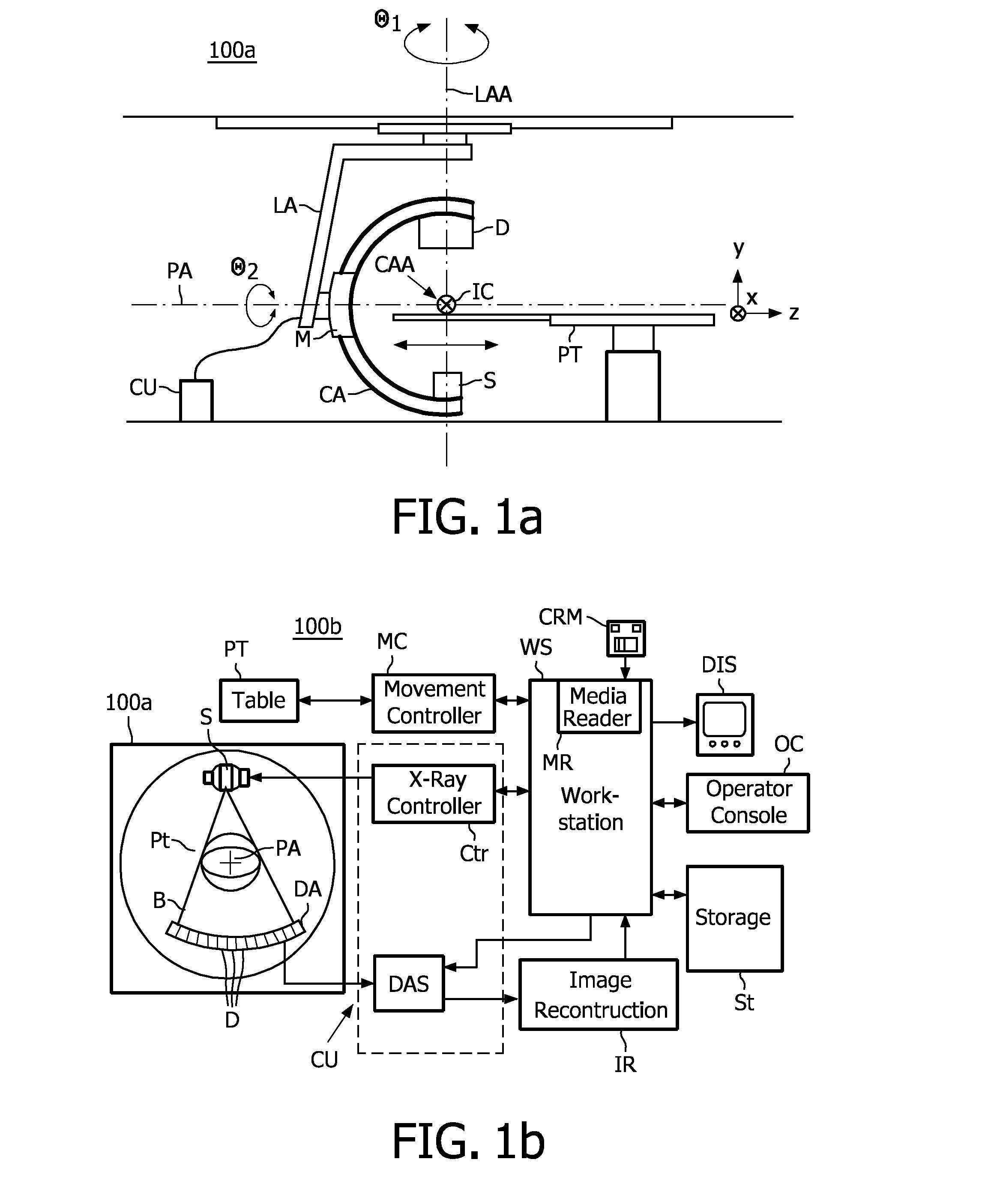
[0032]In FIG. 1a, a conventional setup configuration of a mobile C-arm based rotational X-ray scanner system 100a for use in tomographic X-ray imaging as known from the relevant prior art (e.g. such as disclosed in US 2002 / 0168053 A1) is shown. The depicted CT system comprises an X-ray source S and an X-ray detector D arranged at opposite ends of a C-arm CA which is journally mounted so as to be rotatable about a horizontal propeller axis PA and a horizontal C-arm axis CAA perpendicular to said propeller axis by means of a C-arm mount M, thus allowing said X-ray source and X-ray detector to rotate by a rotational angle (θ1 or θ2, respectively) about the y- and / or z-axis of a stationary 3D C...


PUM


Abstract

The present invention refers to 3D rotational X-ray imaging systems for use in computed tomography (CT) and, more particularly, to a fast, accurate and mathematically robust calibration method for determining the effective center of rotation (I) in not perfectly isocentric 3D rotational C-arm systems and eliminating substantially circular ring artifacts (RA) which arise when using such a CT scanner system for acquiring a set of 2D projection images of an object of interest to be three-dimensionally reconstructed. For this purpose, a C-arm based rotational CT scanner comprising at least one radiation detector (D) having an X-radiation sensitive surface exposed to an X-ray beam emitted by at least one X-ray tube (S), each rotating along a non-ideal circular trajectory (TF, TCD) about an object of interest to be three-dimensionally reconstructed from a set of 2D projection images is used for providing geometrical calibration data by scanning a calibration phantom from a plurality of distinct projection directions and calculating, for each projection direction, the 3D positions of the X-ray tube's focal spot and the X-ray detector's center. For approximating the exact 3D position and angular direction of the axis of rotation about which the at least one X-ray tube and the at least one radiation detector rotate, a circular regression technique using a number of mathematically robust least squares fits is applied.

Description

FIELD OF THE INVENTION[0001]The present invention refers to 3D rotational X-ray imaging systems for use in computed tomography (CT) and, more particularly, to a fast, accurate and mathematically robust calibration method for determining the effective center of rotation in not perfectly isocentric 3D rotational C-arm systems and eliminating substantially circular ring artifacts which arise when using such a CT scanner system for acquiring a set of 2D projection images of an object of interest to be three-dimensionally reconstructed. For this purpose, a C-arm based rotational CT scanner comprising at least one radiation detector having an X-radiation sensitive surface exposed to an X-ray beam emitted by at least one X-ray tube, each rotating along a non-ideal circular trajectory about an object of interest to be three-dimensionally reconstructed from a set of 2D projection images is used for providing geometrical calibration data by scanning a calibration phantom from a plurality of d...

Claims


Application Information

Patent Timeline
Patent Type & Authority Patents(United States)
IPC IPC(8): A61B6/00G01D18/00
CPCA61B6/583A61B6/027
Inventor NOORDHOEK, NICOLAAS JANTIMMER, JAN
Owner KONINK PHILIPS ELECTRONICS NV
Why Eureka
Try Eureka