Insertion of pre-fabricated concentrated windings into stator slots

a concentrated winding and stator technology, applied in the manufacture of stator/rotor bodies, magnets, magnetic bodies, etc., can solve the problems of increasing the number of parts and increasing the cos

Active Publication Date: 2012-08-28
TOYOTA JIDOSHA KK
View PDF8 Cites 14 Cited by
  • Summary
  • Abstract
  • Description
  • Claims
  • Application Information

AI Technical Summary

Benefits of technology

[0007]However, the technique disclosed in JP '610A has the following disadvantages. Specifically, since the stator core is formed of a number of divided cores, a process of combining the divided cores (a process of ring shrink-fitting, etc.) is required, leading to an increase in manufacturing costs. As compared with an integral core, furthermore, the teeth are divided in correspondence with slots. Accordingly, inner-diameter accuracy (roundness and others) and outer-diameter accuracy which are important factors of a motor depend on accumulated tolerance of assembled components. Thus, the accuracy could not be ensured reliably. As a result, motor torque ripple, noise, vibration, and so on increase. The above stator if used in a motor for driving a vehicle is liable to deteriorate drivability.
[0016]The above motor stator manufacturing method and motor stator according to the present invention can provide the following operations and effects.
[0018]When the second part of the coil comes into contact with the first tooth, the first part of the coil has already been inserted in the slot. Thus, the second part can also be inserted smoothly.
[0020]According to the above configuration (3), the second and third teeth are located on both sides of the first tooth and the slot is designed so that, when the second coil is inserted in the slot, the minimum distance between the third tooth and the second trapezoidal coil is larger than the maximum width of the coil. Accordingly, even when the first trapezoidal coil is slid along one side surface of the first tooth in mounting the first coil on the first tooth, the outer peripheral edge of the bottom of the first coil closer to the first tooth will not contact with the third tooth. Thus, the first coil has only to be slid along one side surface of the first tooth, allowing smooth and easy insertion of the first coil into the slot around the first tooth.
[0021]According to the above motor stator (5), even when the first trapezoidal coil is slid along one side surface of the first tooth in mounting the first coil on the first tooth, the outer peripheral edge of the bottom of the first coil closer to the first tooth will not contact with the third tooth. Thus, the first coil has only to be slid along one side surface of the first tooth, allowing smooth and easy insertion of the first coil into the slot around the first tooth.

Problems solved by technology

However, this configuration requires manufacture of different shaped coils, resulting in an increase in the number of parts, thus leading to cost increase.

Method used


Image

  • Insertion of pre-fabricated concentrated windings into stator slots
  • Insertion of pre-fabricated concentrated windings into stator slots
  • Insertion of pre-fabricated concentrated windings into stator slots

Examples


Embodiment Construction

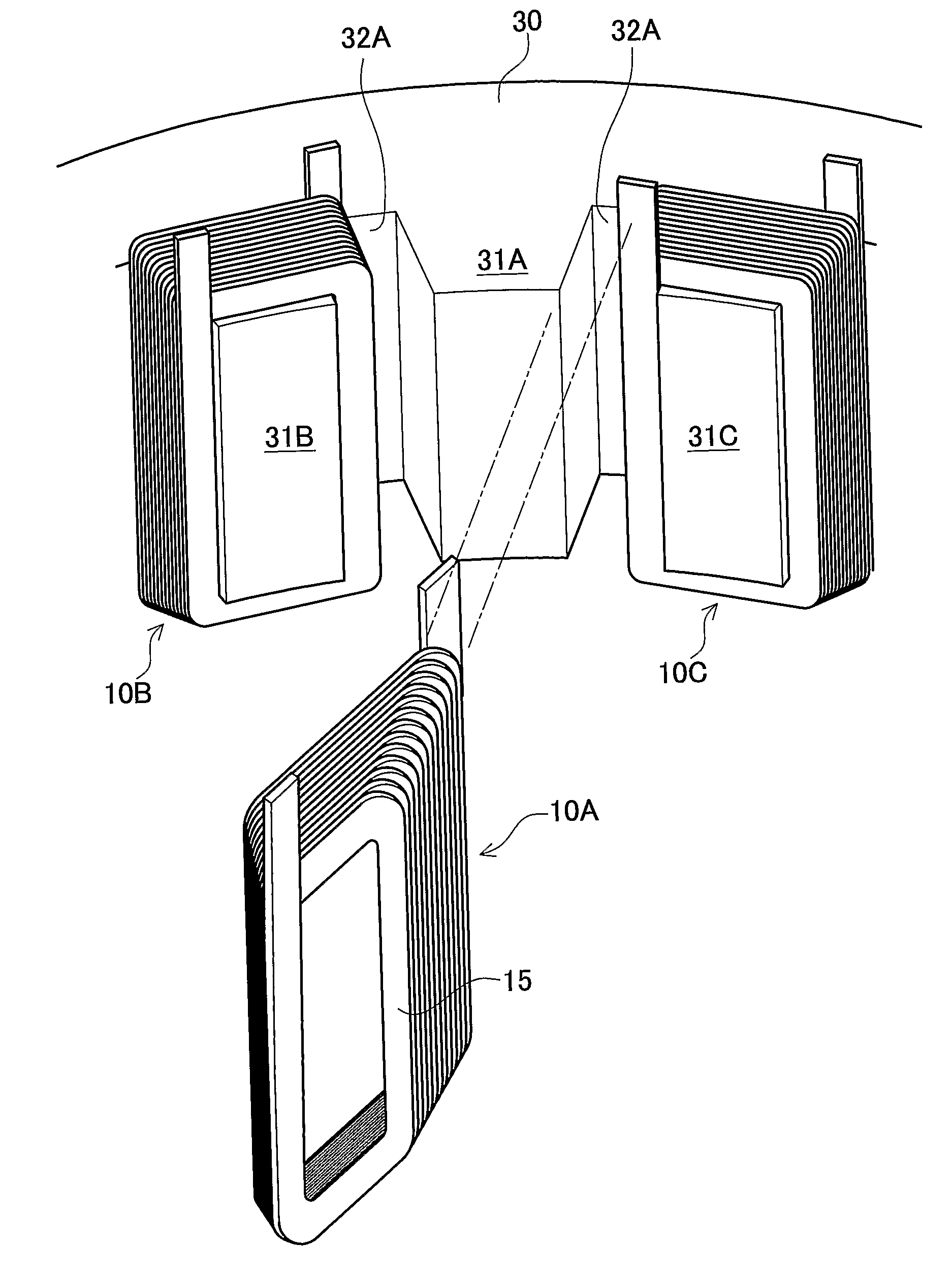
[0034]A detailed description of a preferred embodiment of the present invention will now be given referring to the accompanying drawings. FIG. 9 is a perspective view showing a state that a first coil 10A is to be set in a stator core 30 in the present embodiment.

[0035]Each of the first coil 10A, a second coil 10B, and a third coil 10C is made of a flat rectangular conductor 15 edgewise wound in spiral form. The conductor 15 is 1.0 mm in thickness and 5.0 mm in width in the present embodiment. Each of the coils 10A, 10B, and 10C has trapezoidal end faces along a short side and rectangular end faces along a long side. The conductor 15 is made of metal exhibiting excellent conductivity, such as copper, and coated with an insulation coating. This insulation coating is provided by enamel coating or resin coating, such as polyimide and amidimid, which ensures insulation.

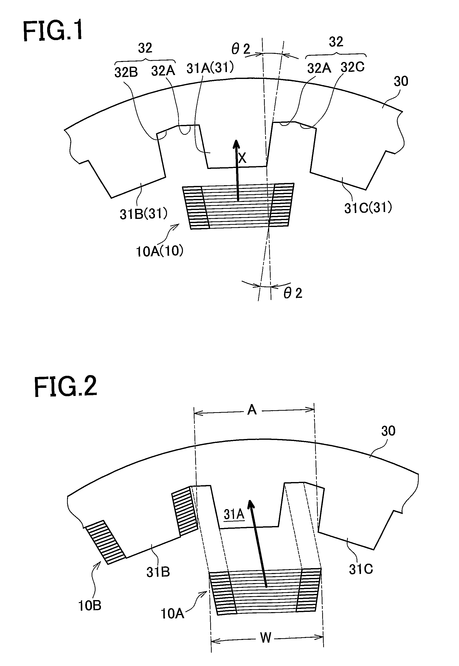
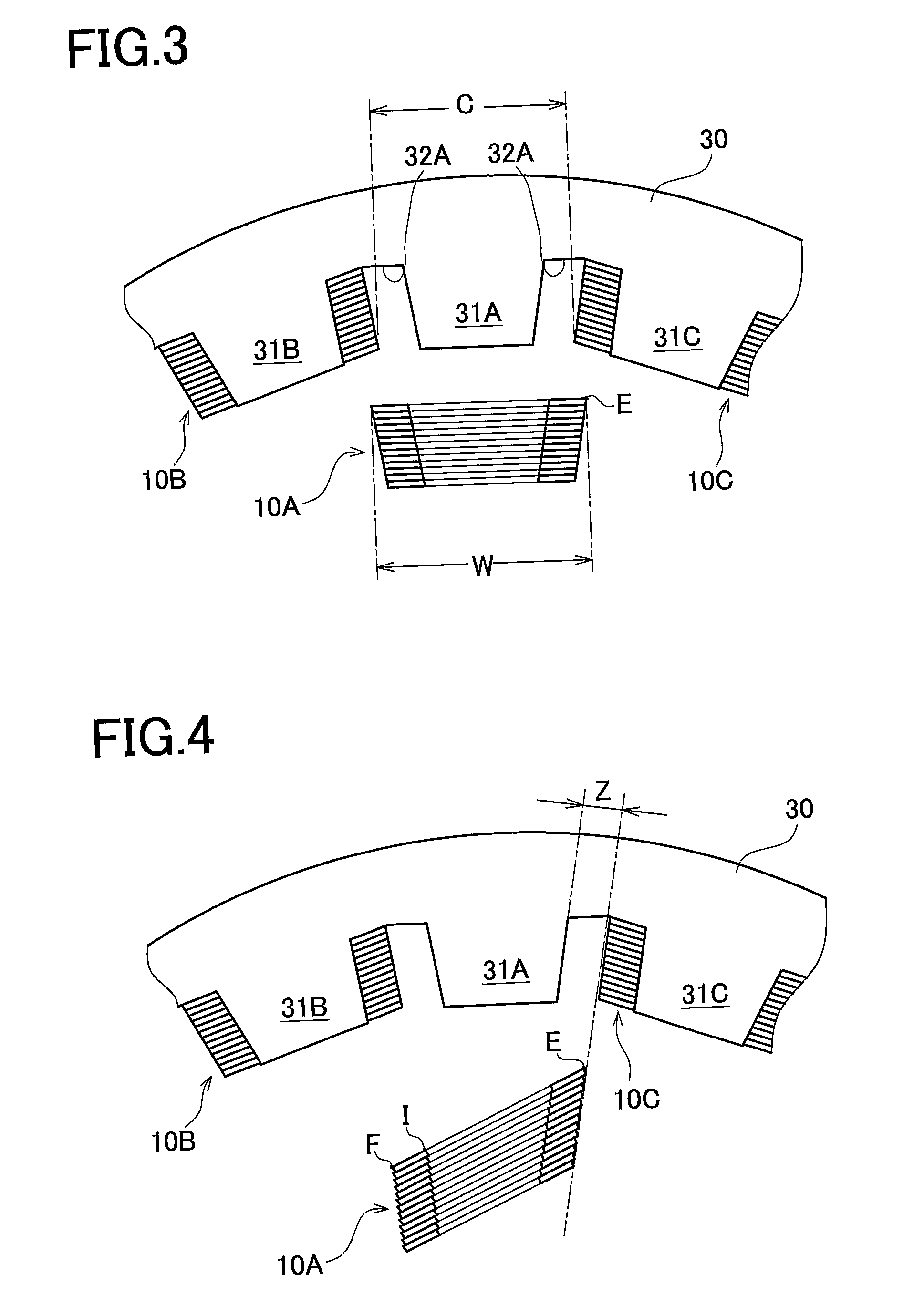
[0036]A stator core 30 is constituted of annular disc-shaped laminated metal sheets and formed with teeth 31 (31A, 31B,...


PUM

PropertyMeasurementUnit
thicknessaaaaaaaaaa
thicknessaaaaaaaaaa
shapeaaaaaaaaaa

Abstract

A method for manufacturing a motor stator including individually mounting second and third coils on second and third teeth that are located on both sides of a first tooth, deforming a first coil with an air core before it is mounted on the first tooth, and inserting a first part of the deformed coil into a slot on one side of the first tooth, and inserting a second part of the deformed coil into the slot on the other side of the first tooth.

Description

[0001]This is a 371 national phase application of PCT / JP2008 / 053716 filed 25 Feb. 2008, claiming priority to Japanese Patent Application No. 2007-056092 filed 6 Mar. 2007, the contents of which are incorporated herein by reference.TECHNICAL FIELD[0002]The present invention relates to a method of manufacturing a motor stator in which trapezoidal concentrated winding coils made of rectangular conductors set in an integral core with less limitation in the number of poles.BACKGROUND ART[0003]Many of stators used for motor include coils each of which is formed of a wound conductor having a circular cross-section. As the demands for an increase in efficiency and a reduction in size and weight of a motor have grown in recent years, a high space factor of a conductor in a slot of a stator has been, required.[0004]For mounting a circular cross-section conductor on teeth of a stator core, JP 11(1999)-032457A discloses a configuration that trapezoidal coils and parallel coils are set alternate...

Claims


Application Information

Patent Timeline
Patent Type & Authority Patents(United States)
IPC IPC(8): H02K15/00
CPCH02K15/066Y10T29/49073Y10T29/49012Y10T29/49071Y10T29/49009H02K15/0435H02K3/48H02K3/18H02K1/165
Inventor FUBUKI, SHINGOHARADA, KENJI
Owner TOYOTA JIDOSHA KK
Why Eureka
Try Eureka