
Two-stage reconstituting injector

a two-stage reconstituting and injector technology, applied in the field of injectors, can solve the problems of increasing the risk of inadequate medication handling and clogging of needles, and achieve the effect of convenient and effective delivery of medicaments

Active Publication Date: 2012-08-28
ANTARES PHARMA INC
View PDF6 Cites 95 Cited by
  • Summary
  • Abstract
  • Description
  • Claims
  • Application Information

AI Technical Summary

Benefits of technology

The invention is an injector that allows for the easy and effective delivery of a liquid medicament to a patient. It includes a container with two chambers, an injection conduit, a transfer mechanism, a firing mechanism, and an energy source. The injector can be used in two stages of operation: a first stage to pierce the container and transfer the fluid to the injection conduit, and a second stage to fire the fluid and direct it into the patient. The injector is designed to be user-friendly and safe, with a retractable guard for easy use and a trigger device for reliable operation. The invention also allows for the reconstitution of the medicament just before injection, making it easy to prepare for use.

Problems solved by technology

This can be due to the insolubility of the drug in the vehicle or medium in which it is stored.
The particulates can potentially clog the needle, and this is particularly problematic in cases when the liquid pharmaceutical preparation containing insoluble particles is self-administered or administered in the home by non-professional care-givers.
However when such pharmaceutical preparations are self-administered or administered in the home by non-professional care-givers, the risk for inadequate handling of the medication increases since the injection of such formulations requires that the administrator be able to adequately resuspend any settled material and clear the needle to ensure proper drug delivery.

Method used


Image

  • Two-stage reconstituting injector
  • Two-stage reconstituting injector
  • Two-stage reconstituting injector

Examples


Embodiment Construction

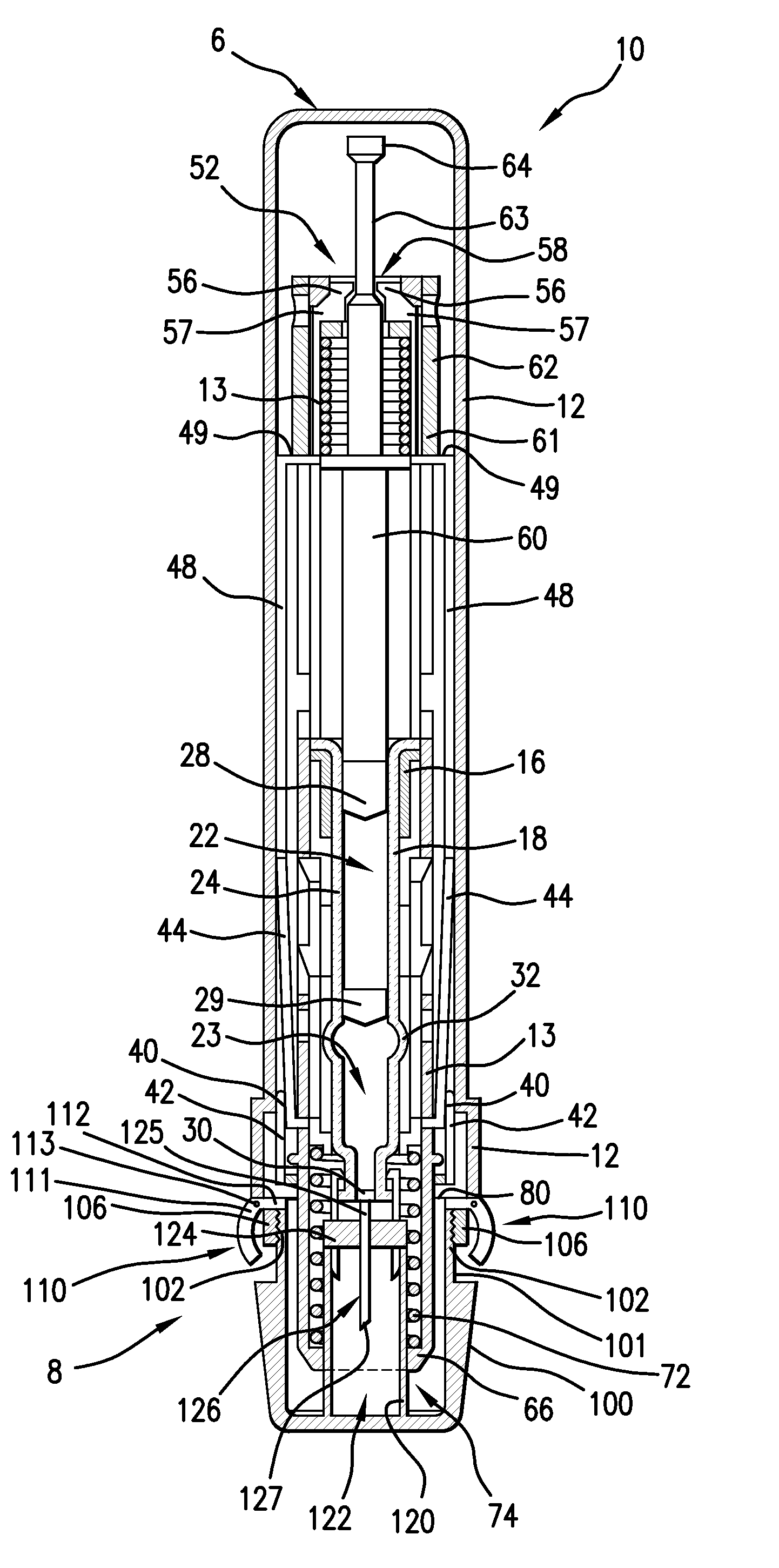
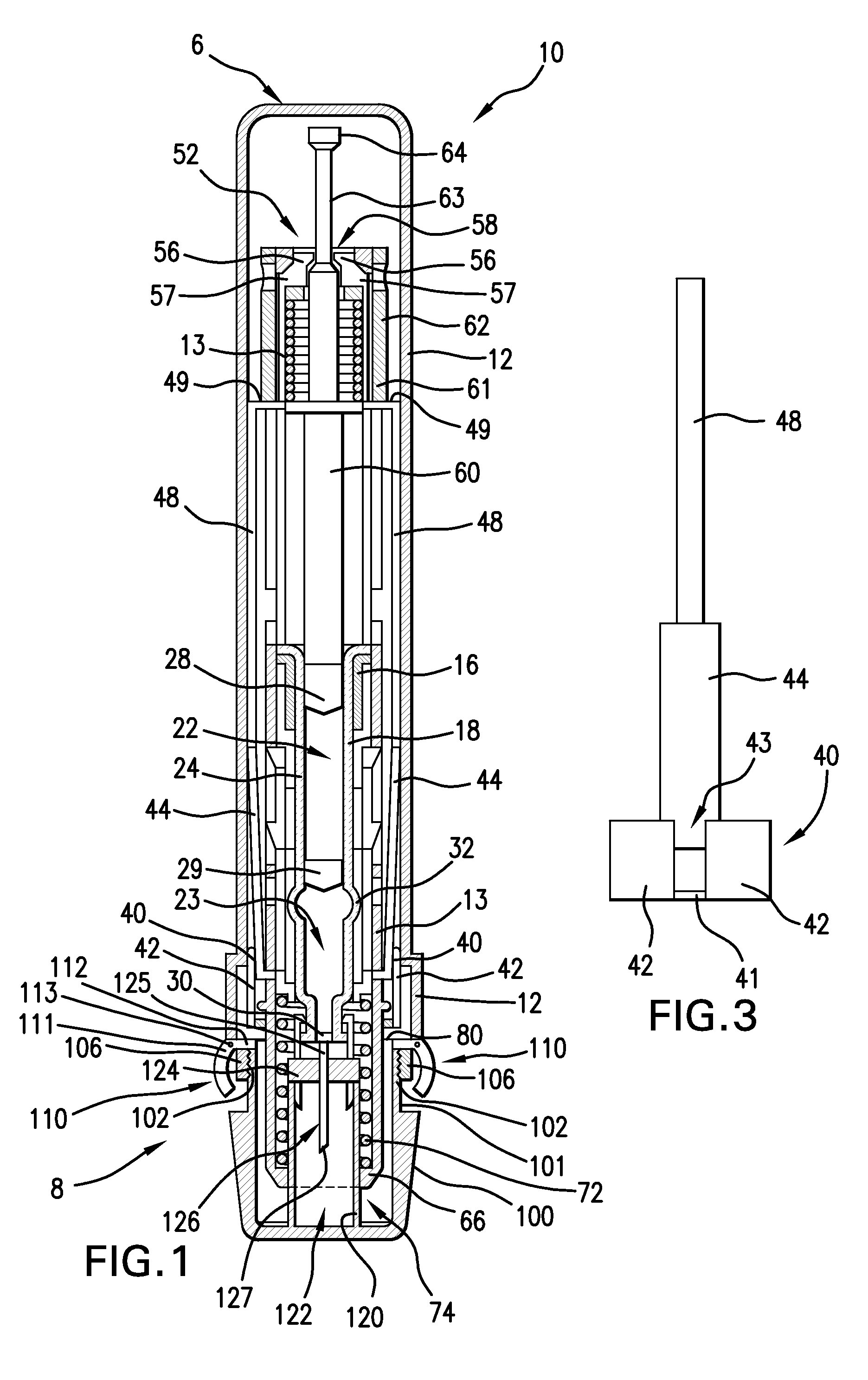
[0022]Referring to FIG. 1, a preferred embodiment of an injector 10 has a tubular outer housing 12 having a proximal end 6 and a distal end 8, and configured for allowing a user to handle the injector 10 and position the injector near or adjacent an injection location of a patient. The outer housing 12 preferably houses most of the components of the injector 10.

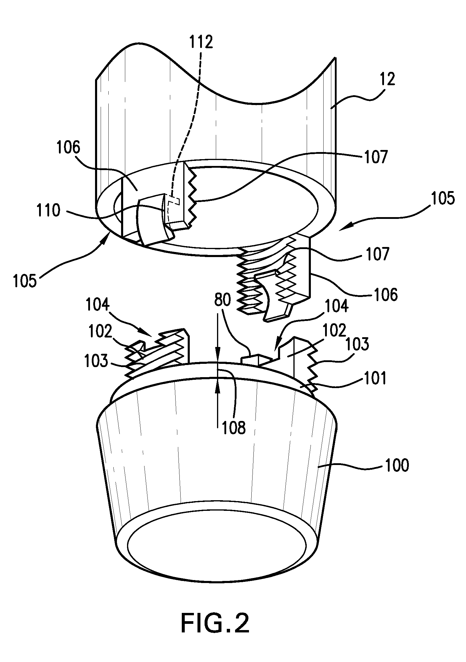
[0023]A cap 100 is associated with the outer housing 12 at the distal end 8 and is configured for covering an injection conduit, which can be a needle 126, or a jet nozzle, for example. The cap 100 preferably includes engagement portions configured for removable engagement with outer housing 12. As shown in the preferred embodiment of FIGS. 1 and 2, the cap 100 preferably includes a radially recessed neck 101 extending a distance 108 from the proximal end thereof. The neck 101 preferably has a smaller diameter than the remaining portion of the cap 100, but can have the same or larger diameter in other embodiments. A pair of e...


PUM


Abstract

An injector for injecting a medicament into a patient. The injector includes a container defining a first chamber, which contains a fluid therein, and a second chamber. The injector also includes an injection conduit configured for directing the fluid fired from the container into the patient. A transfer mechanism is operable by a user to transfer the fluid from the first chamber to the second chamber in a first stage of operation, and a firing mechanism is operable by the user for firing the fluid from the second chamber through the injection conduit in a second stage of operation. An energy source is in powering association with the firing mechanism to drive firing mechanism in the first and second stages.

Description

[0001]This application is a 371 filing of International Patent Application PCT / US2007 / 067986 filed May 2, 2007, which claims the benefit of application No. 60 / 796,939 filed May 3, 2006.FIELD OF THE INVENTION[0002]The present invention relates to an injector, and more particularly to an injector in which materials from at least two compartments are contained before the injection is made.BACKGROUND OF THE PRESENT INVENTION[0003]Known injection devices for injection of medicaments into a patient include traditional hypodermic needle syringes, needle-free jet injectors like the ones disclosed in U.S. Pat. Nos. 5,599,302; 5,062,830; and 4,790,824; needle-assisted injectors, such as those described in U.S. Patent Publication No. 2005 / 0033234; and self-injectors or autoinjectors like the ones disclosed in U.S. Pat. Nos. 4,553,962 and 4,378,015, and PCT Publications WO 95 / 29720 and WO 97 / 14455.[0004]The liquid medicament preparations that are injected from such injection devices are also kn...

Claims


Application Information

Patent Timeline
Patent Type & Authority Patents(United States)
IPC IPC(8): A61M37/00
CPCA61M5/2066A61M5/2466A61M5/3202A61M5/19A61M5/30A61M5/31596A61M5/2033A61M5/3204A61M5/326A61M2005/2474A61M2005/2073A61M2005/3125A61M2005/2013
Inventor KRAMER, THOMAS E.SADOWSKI, PETER L.
Owner ANTARES PHARMA INC
Learn More