Method and apparatus for high quality video motion adaptive edge-directional deinterlacing

a motion adaptive edge-directional and video technology, applied in the field of methods and apparatus for deinterlacing interlaced video, can solve the problems of reducing the vertical resolution of all spatial methods, requiring temporal interpolation in the creation of frames, and affecting the quality of the video

Active Publication Date: 2012-09-04
ATI TECH INC
View PDF101 Cites 34 Cited by
  • Summary
  • Abstract
  • Description
  • Claims
  • Application Information

AI Technical Summary

Problems solved by technology

Because the sequential fields are different in time, however, creating a frame often requires temporal interpolation, especially when motion exists.
Bobbing and line doubling, however, may both suffer staircase effects (also known as “shredding”) on areas that feature diagonal lines and edges.
All spatial methods suffer reduced vertical resolution where the lost resolution was present in the missing pixels.
This loss of resolution is especially apparent in still areas.
As noted above, however, this method does not work well when there is motion.
This, however, can be very expensive and has marginal quality improvement over other methods.
Conventional motion adaptive edge-directional deinterlacing methods, however, are not without their problems.
For example, known solutions require dedicated hardware, which does not fully leverage the shader (and thus increases the area of silicon).
Furthermore, using the shader for the entire motion adaptive edge-directional deinterlacing procedure consumes a lot of power, which is not always doable on low-end graphical processing units (“GPUs”).
In some implementations, it requires too many instructions to deinterlace high quality video in real time.

Method used


Image

  • Method and apparatus for high quality video motion adaptive edge-directional deinterlacing
  • Method and apparatus for high quality video motion adaptive edge-directional deinterlacing
  • Method and apparatus for high quality video motion adaptive edge-directional deinterlacing

Examples


Embodiment Construction

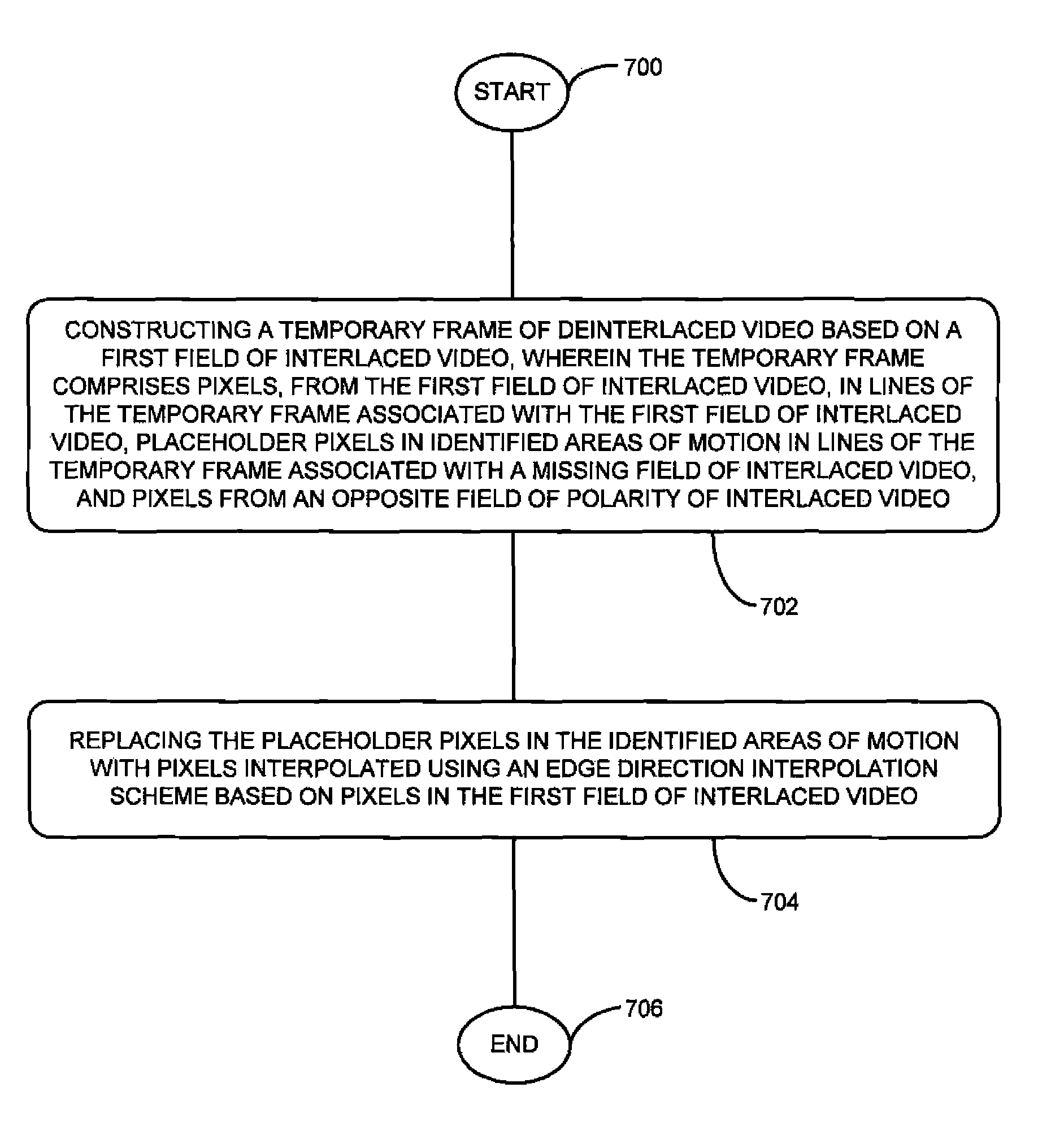
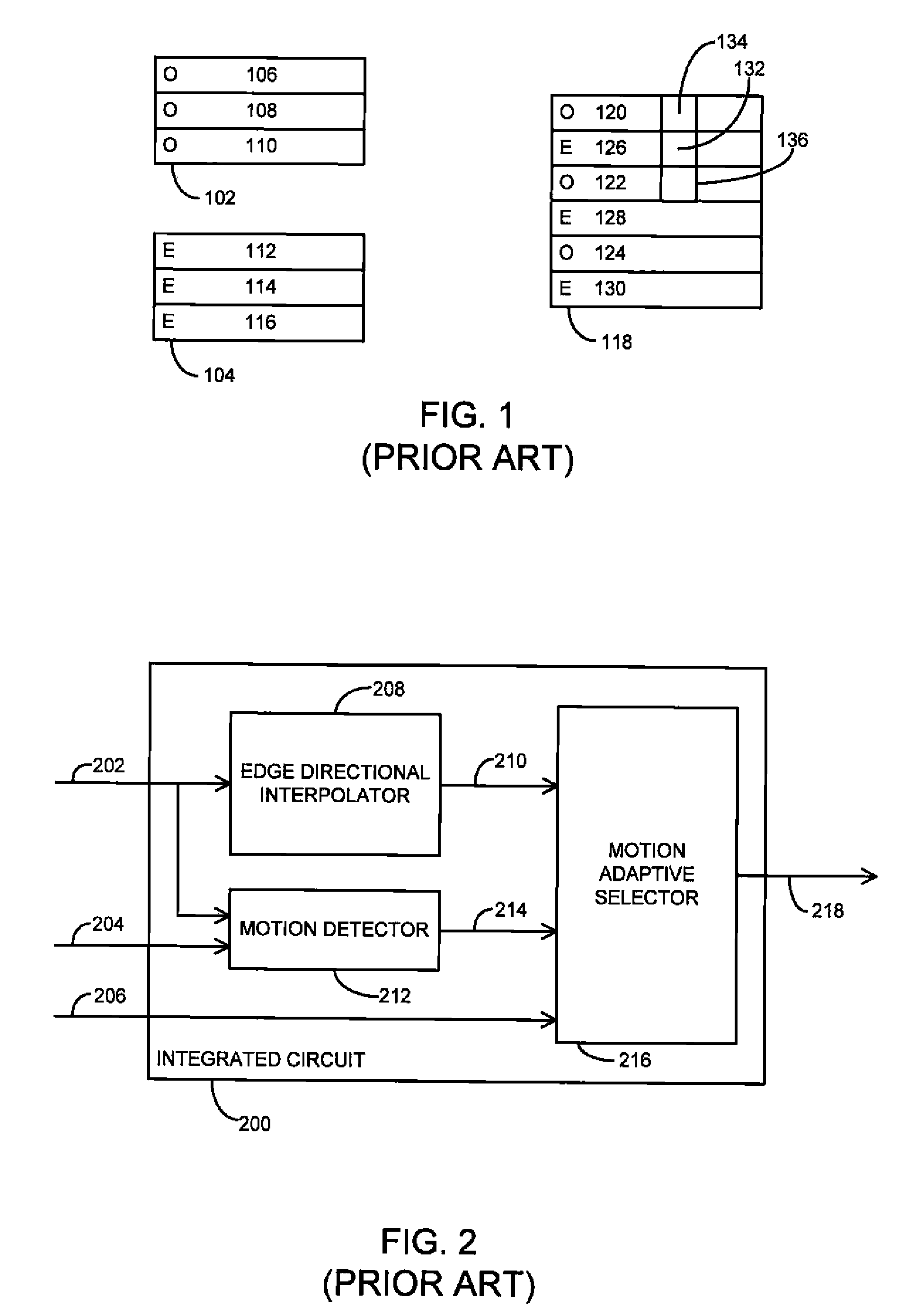
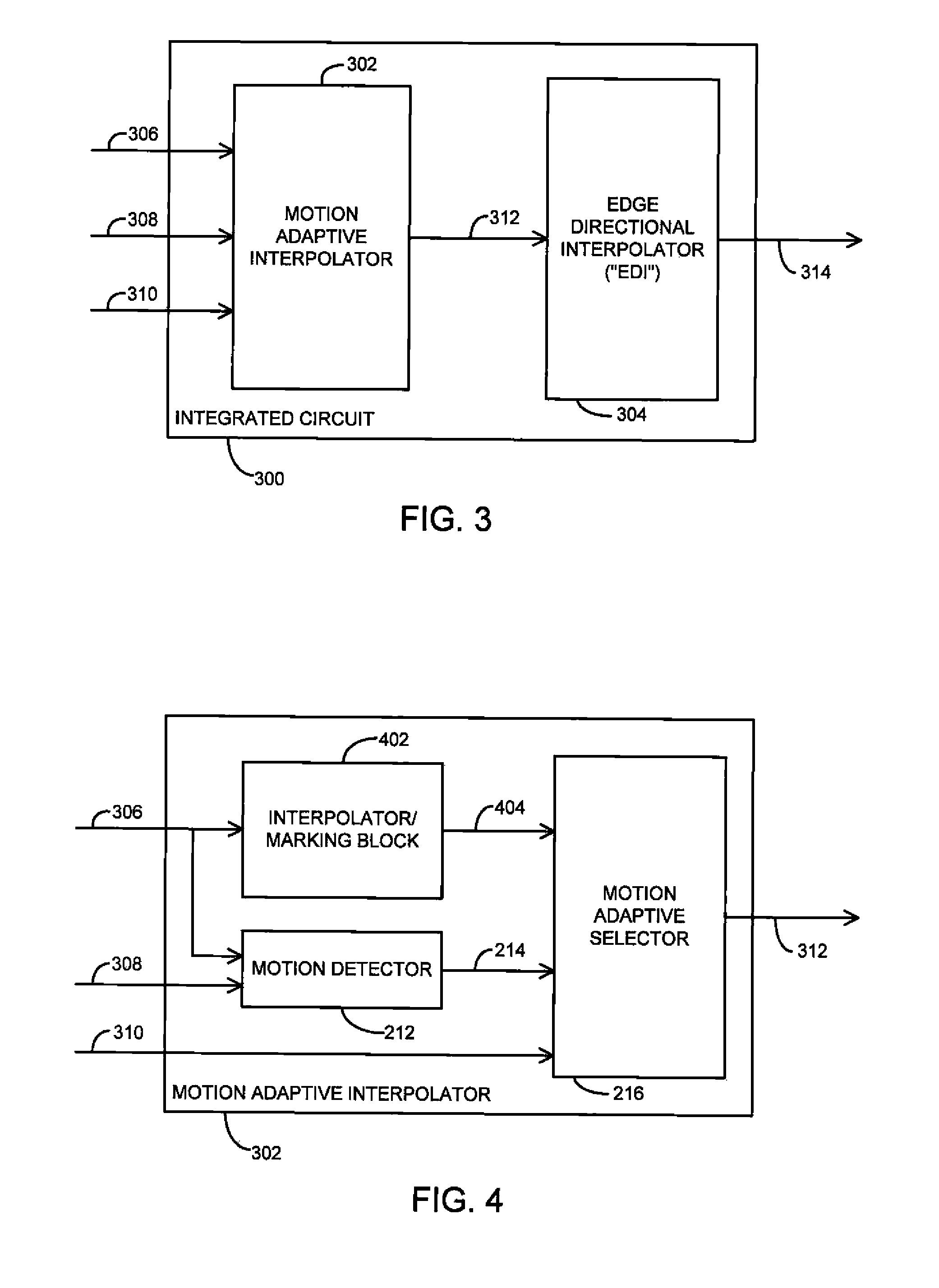
[0024]Briefly, a method for deinterlacing video includes constructing a temporary frame of deinterlaced video based on a first (i.e., current) field of interlaced video, wherein the temporary frame includes pixels in lines of the temporary frame associated with the first field of interlaced video, placeholder pixels in identified areas of motion in lines of the frame associated with a missing field of interlaced video, and pixels from an opposite field of polarity of interlaced video in areas without motion. The method further includes replacing the placeholder pixels in the identified areas of motion with pixels interpolated using an edge direction interpolation scheme based on pixels in the first held of interlaced video, resulting in a reconstructed frame. In one example, a motion adaptive interpolator may construct the temporary frame, and an edge directional interpolator may generate the reconstructed / deinterlaced the frame.

[0025]In another example, the method and apparatus may...


PUM


Abstract

A method for deinterlacing video includes constructing a temporary frame of deinterlaced video based on a first (i.e., current) field of interlaced video, wherein the temporary frame includes pixels in lines of the temporary frame associated with the first field of interlaced video, placeholder pixels in identified areas of motion in lines of the frame associated with a missing field of interlaced video, and pixels from an opposite field of polarity of interlaced video in areas without motion. The method further includes replacing the placeholder pixels in the identified areas of motion with pixels interpolated using an edge direction interpolation scheme based on pixels in the first field of interlaced video, resulting in a reconstructed frame. In one example, a motion adaptive interpolator may construct the temporary frame, and an edge directional interpolator may generate the reconstructed / deinterlaced the frame.

Description

FIELD OF THE INVENTION[0001]This disclosure relates generally to methods and apparatus for deinterlacing interlaced video, and more particularly, to methods and apparatus that deinterlace video utilizing motion adaptive edge-directional techniques.BACKGROUND OF THE INVENTION[0002]Computer monitors are often non-interlaced or progressive type display devices, so video images or graphic images must be displayed by sequentially displaying each successive line or pixel data sequentially for a frame of an image. In contrast, interlaced display devices, such as conventional television displays, typically display images using even and odd line interlacing. The process of producing one progressive frame on every incoming interlaced field is called deinterlacing. In other words, deinterlacing is the process of converting a sequence of fields into a sequence of frames.[0003]FIG. 1, for example, shows a first field 102 and a second field 104. The first field 102 contains the odd lines 106 thro...

Claims


Application Information

Patent Timeline
Patent Type & Authority Patents(United States)
IPC IPC(8): H04N11/20G06K9/32
CPCH04N7/012H04N5/142H04N5/144H04N7/0137H04N7/0142
Inventor WEI, JEFFGLEN, DAVID
Owner ATI TECH INC
Why Eureka
Try Eureka